
Stage device, exposure apparatus, exposure method and device manufacturing method

a technology of exposure apparatus and manufacturing method, which is applied in the direction of photomechanical treatment, printing, instruments, etc., can solve the problems of defective device production, exposure failure, and defect in the pattern formed on the substrate, so as to suppress the occurrence or appearance of defective device, suppress the influence of heat of vaporization, and suppress the effect of exposure failur

Inactive Publication Date: 2013-02-19
NIKON CORP
View PDF45 Cites 0 Cited by
  • Summary
  • Abstract
  • Description
  • Claims
  • Application Information

AI Technical Summary

Benefits of technology

The present invention provides a stage apparatus that reduces the impact of liquid vaporization heat, an exposure apparatus and method that prevents exposure failure, and a device production method that reduces defective device production. These improvements help to improve the overall quality and efficiency of the process.

Problems solved by technology

That is, exposure failure might occur, for example, such that a defect appears in the pattern to be formed on the substrate.
As a result, there is such a possibility that a defective device might be produced.

Method used


Image

  • Stage device, exposure apparatus, exposure method and device manufacturing method
  • Stage device, exposure apparatus, exposure method and device manufacturing method
  • Stage device, exposure apparatus, exposure method and device manufacturing method

Examples


first embodiment

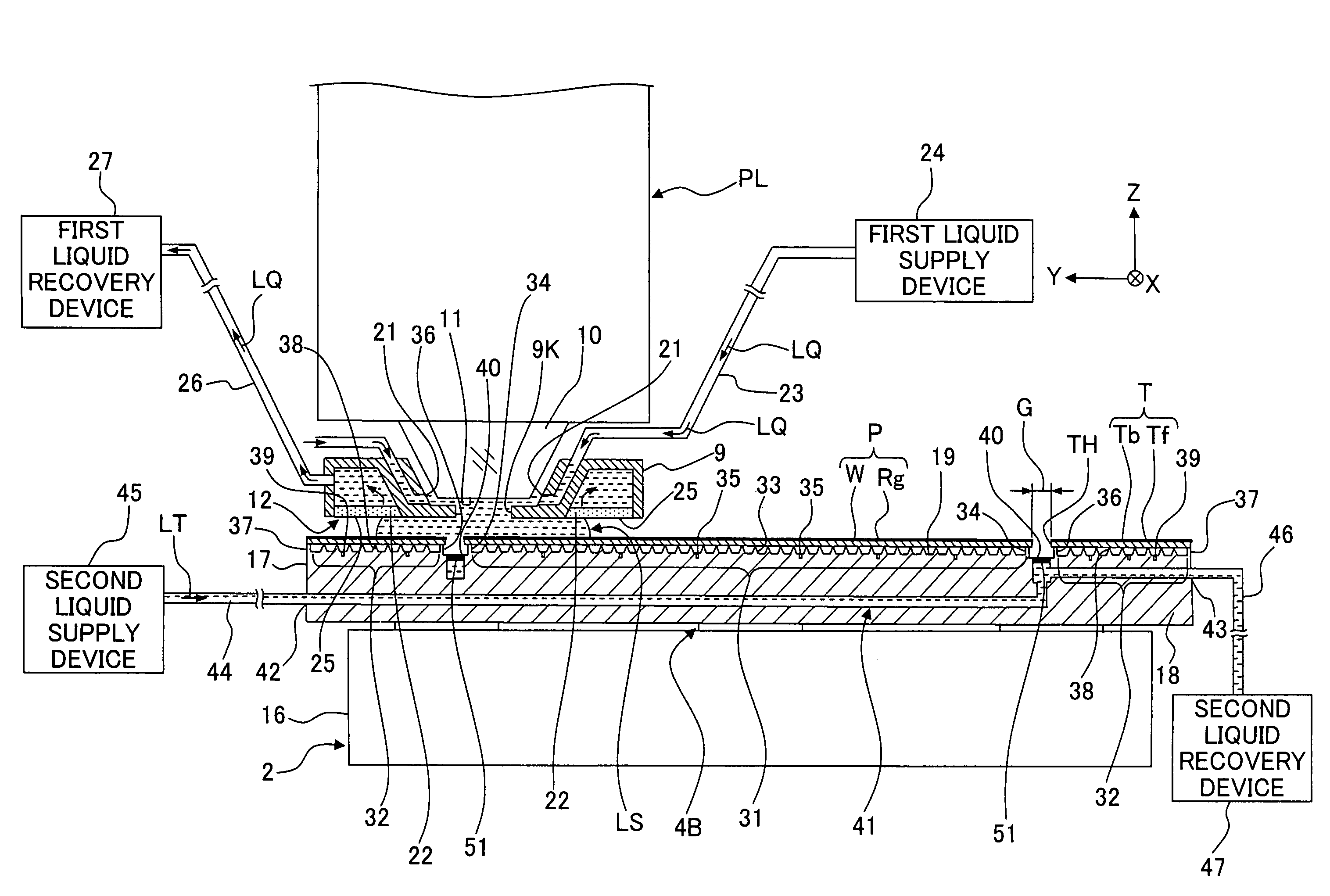
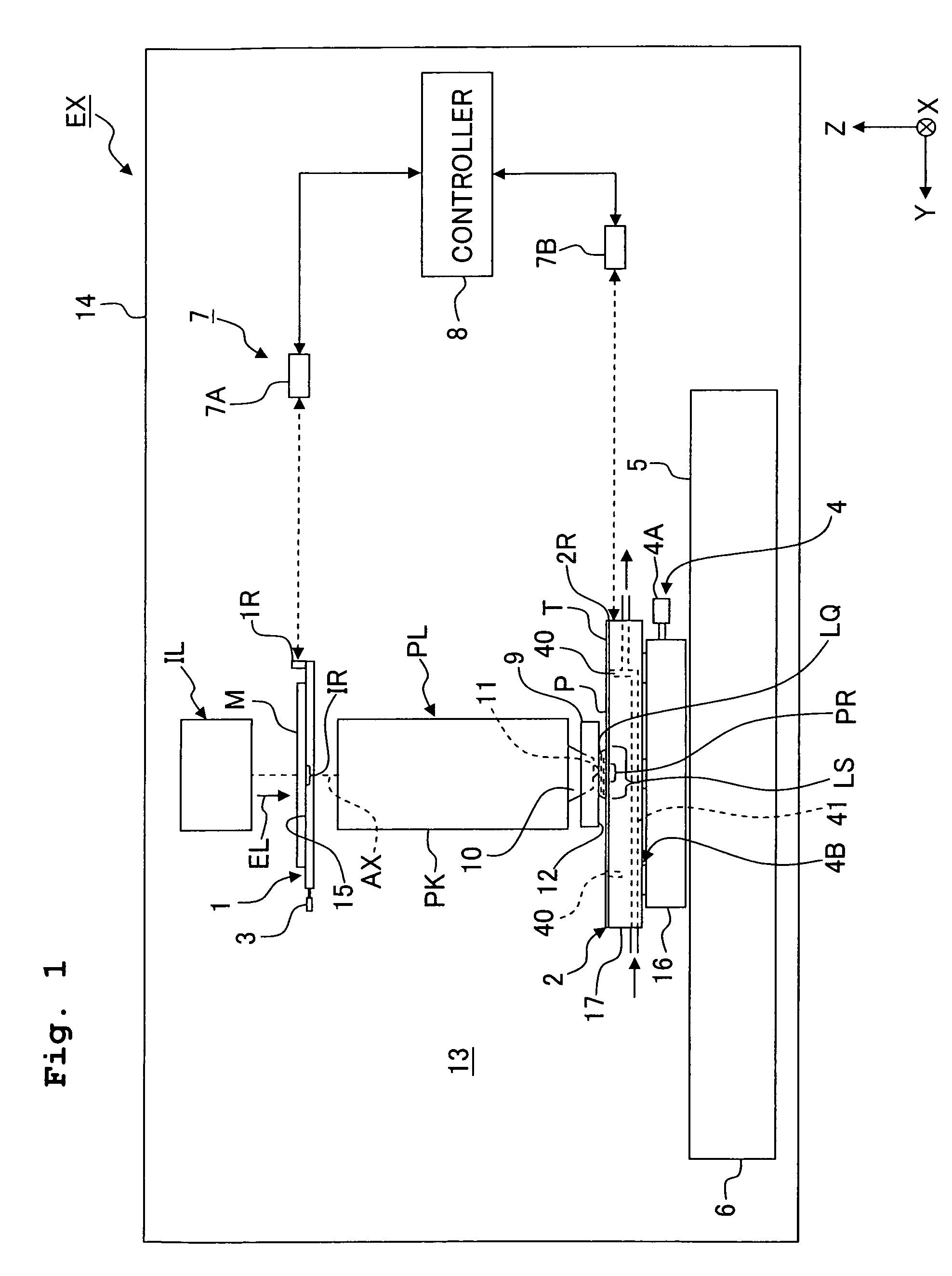
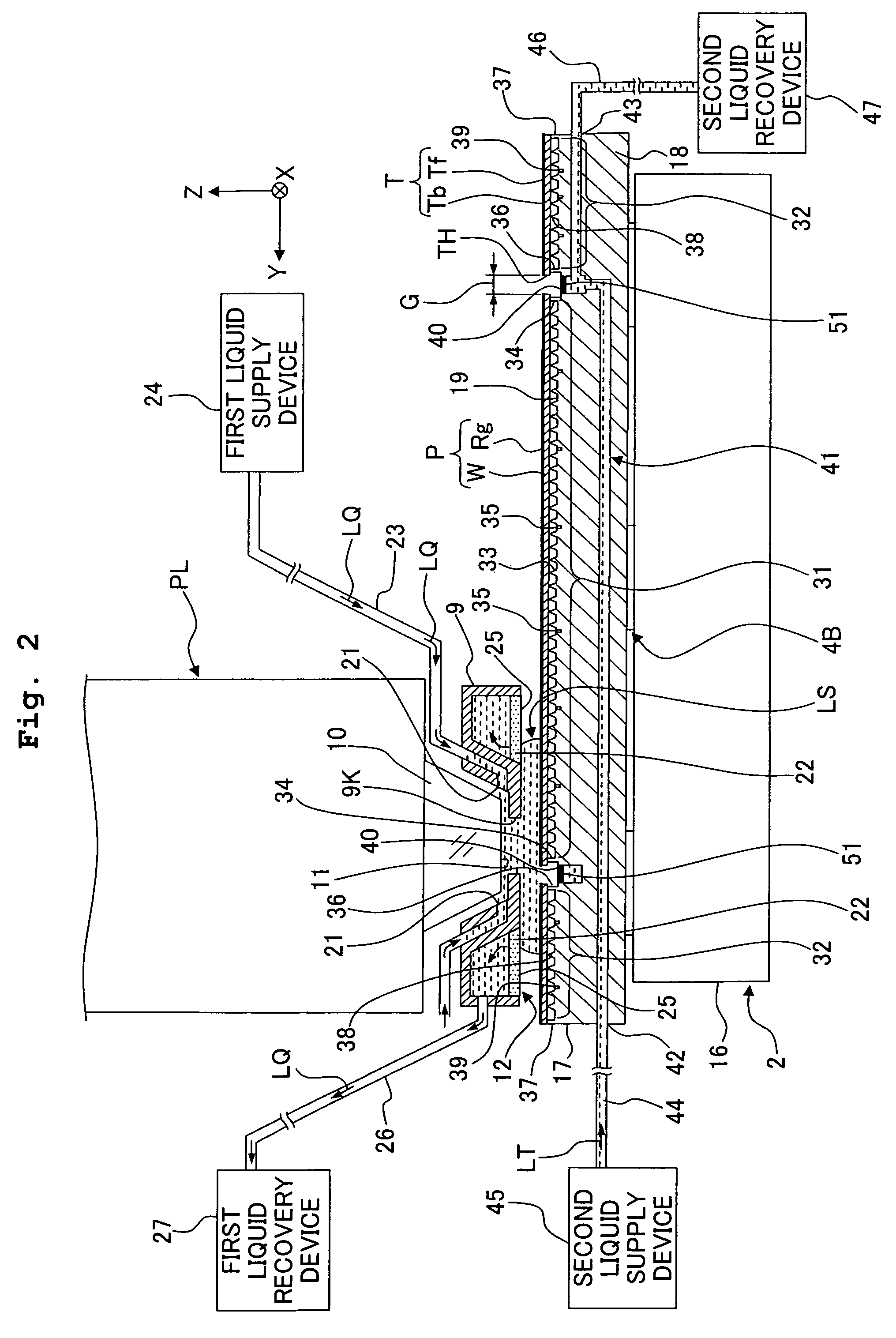
[0026]A first embodiment will be explained. FIG. 1 shows a schematic construction of an exposure apparatus EX according to the first embodiment. With reference to FIG. 1, the exposure apparatus EX includes a mask stage 1 which is movable while holding a mask M; a substrate stage 2 which has a substrate table 17 for holding a substrate P and which is movable while holding the substrate P with the substrate table 17; a first driving system 3 which moves the mask stage 1; a second driving system 4 which moves the substrate stage 2; an interferometer system 7 which measures position information about each of the stages 1, 2; an illumination system IL which illuminates the mask M with an exposure light EL; a projection optical system PL which projects, onto the substrate P, an image of a pattern of the mask M illuminated with the exposure light EL; and a controller 8 which controls the overall operation of the exposure apparatus EX.

[0027]The exposure apparatus EX further includes a chamb...

second embodiment

[0110]Next, a second embodiment will be explained. In the following explanation, the constitutive components or parts, which are same as or equivalent to those of the embodiment described above, are designated by the same reference numerals, any explanation of which will be simplified or omitted.

[0111]FIG. 7 shows a schematic construction illustrating an example of an exposure apparatus EX according to the second embodiment. The exposure apparatus EX according to the second embodiment is an exposure apparatus including a substrate stage 2 which is movable while holding a substrate P, and a measuring stage 70 which does not hold the substrate P and which is movable while mounting thereon a measuring unit or device and a measuring member capable of executing a predetermined measurement in relation to the exposure, as disclosed, for example, in U.S. Pat. No. 6,897,963 and European Patent Application Publication No. 1713113.

[0112]The measuring stage 70 has a stage body 71, and a measuri...


PUM


Abstract

A stage apparatus includes a table member which holds a first object; a liquid recovery port which is provided on the table member and via which a first liquid is recovered; a first flow passage which is formed in the table member, which is connected to the liquid recovery port, and through which a second liquid flows to adjust a temperature of the table member; and a pressure-adjusting device which adjusts a pressure of the first flow passage. The stage apparatus is capable of suppressing the temperature change which would be otherwise caused by the heat of vaporization. An exposure apparatus including the stage apparatus is provided.

Description

CROSS-REFERENCES TO RELATED APPLICATIONS[0001]This application claims the benefit of priority of Japanese Patent Application No. 2008-025493 filed on Feb. 5, 2008 and U.S. Provisional Application Ser. No. 61 / 064,141 filed on Feb. 19, 2008, the entire disclosures of which are incorporated herein by reference.BACKGROUND OF THE INVENTION[0002]1. Field of the Invention[0003]The present invention relates to a stage apparatus, an exposure apparatus, an exposure method, and a method for producing a device.[0004]2. Description of the Related Art[0005]In relation to the exposure apparatus to be used in the photolithography step, a liquid immersion exposure apparatus is known, which exposes a substrate with an exposure light (exposure light beam) through or via a liquid as disclosed in United States Patent Application Publication No. 2005 / 0219488. The liquid immersion exposure apparatus is provided with a stage apparatus or device which holds the substrate at the back surface of the substrate...

Claims


Application Information

Patent Timeline
Patent Type & Authority Patents(United States)
IPC IPC(8): G03B27/58G03B27/52G03B27/42
CPCG03F7/70341G03F7/70875G03F7/70891H01L21/027
Inventor NAGASAKA, HIROYUKI
Owner NIKON CORP
Learn More