Optical access system and optical line terminal
a technology of optical access system and optical line terminal, which is applied in the direction of transmission, multiplex communication, electrical equipment, etc., can solve the problems of reducing reducing the phase ratio of data transmission, and taking a long time to complete the discovery of all the onus b, so as to prevent the efficiency of data transmission from dropping
- Summary
- Abstract
- Description
- Claims
- Application Information
AI Technical Summary
Benefits of technology
Problems solved by technology
Method used
Image
Examples
first embodiment
[0047
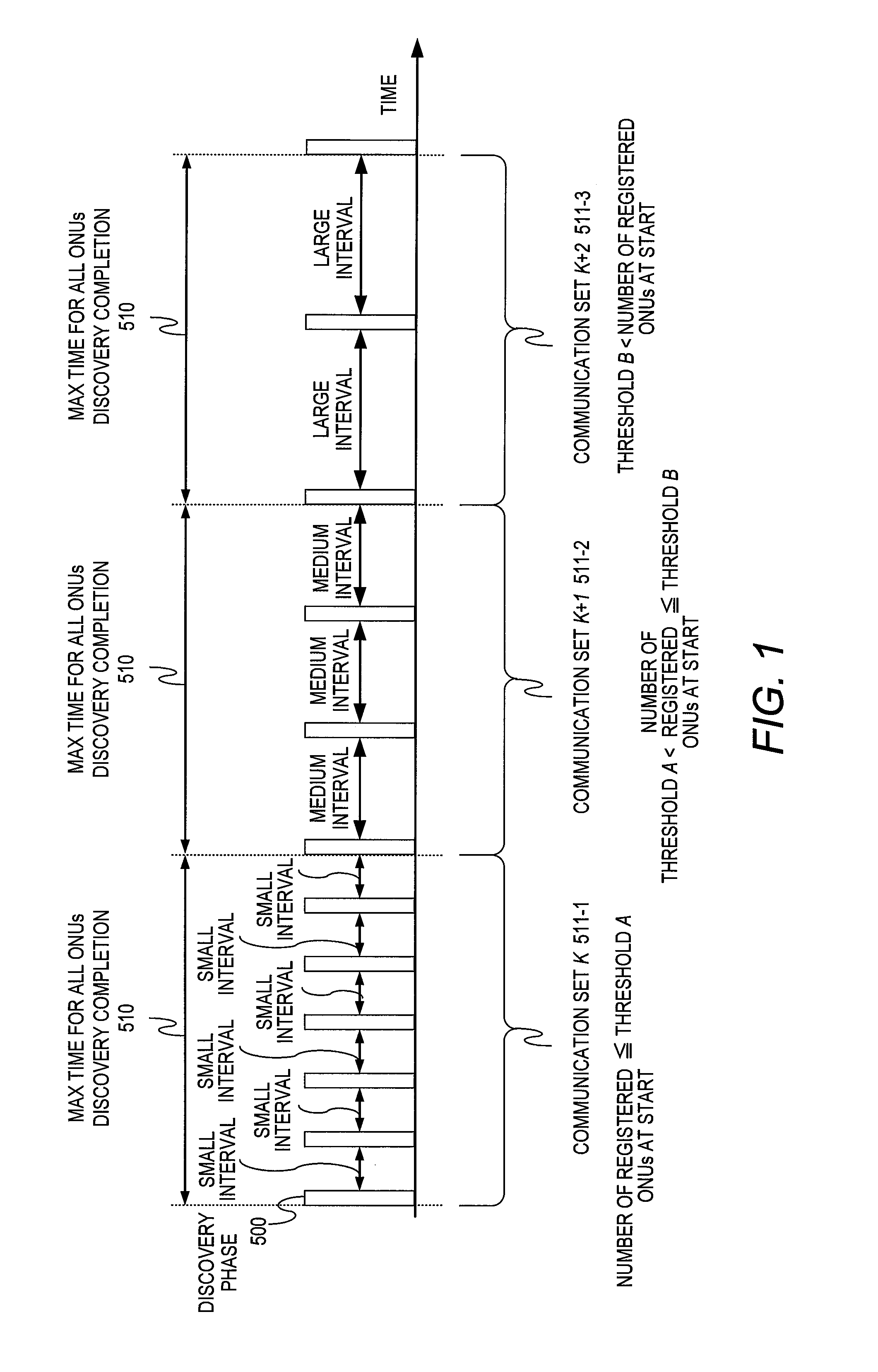
[0048]Described in a first embodiment of this invention is a method of cutting short the time required to complete discovery for all ONUs by dynamically changing the time interval between discovery phases (discovery phase frequency).
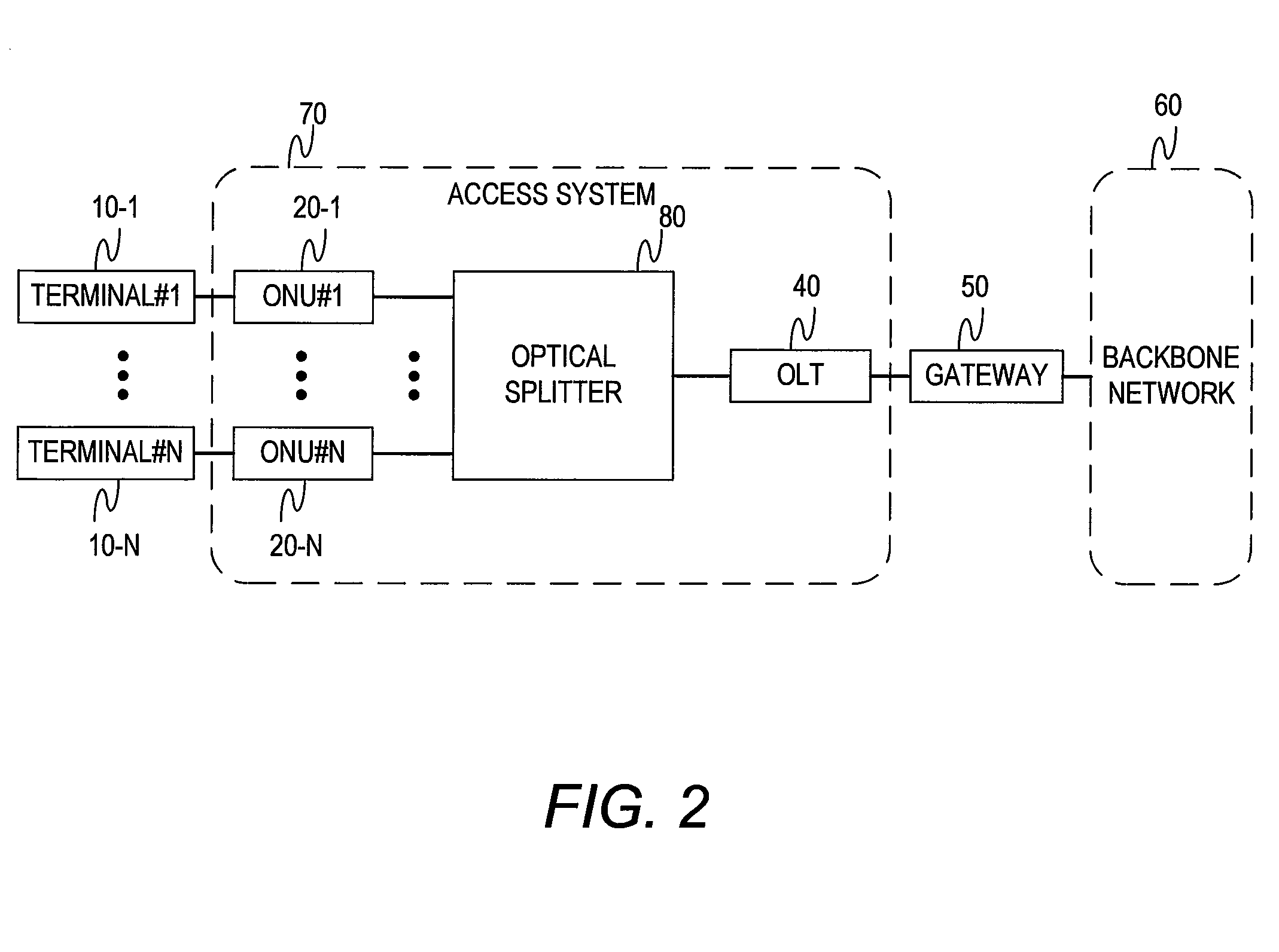
[0049]FIG. 2 is a diagram illustrating a configuration example of an optical network system according to the first embodiment of this invention.
[0050]An optical access system 70 has the optical network units (ONUs) 20, the optical splitter 80, and the optical line terminal (OLT) 40.
[0051]The optical access system 70 has as many optical network units (ONUs) 20 as the number of users, and the plurality of ONUs 20 are respectively connected to user terminals 10 to communicate with the user terminals 10. The optical line terminal (OLT) 40 is connected to the gateway 50 to communicate with the backbone network 60 via the gateway 50. The plurality of ONUs 20 and the OLT 40 are connected to each other via the optical splitter 80, which is a passive device ...
second embodiment
[0081
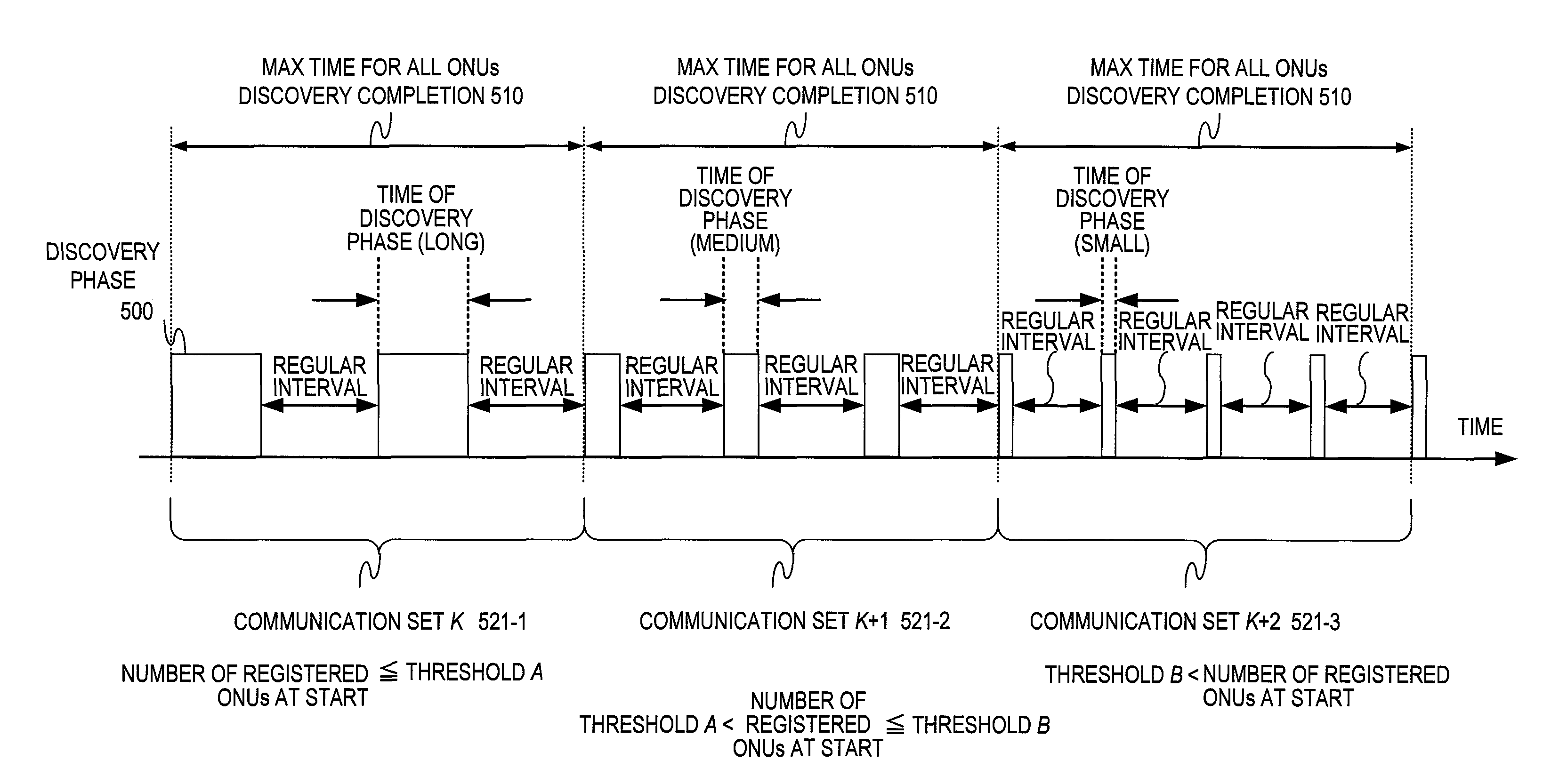
[0082]A second embodiment of this invention is described next which deals with a method of cutting short the time required to complete discovery for all the ONUs 20 by dynamically changing the length of a single discovery phase, instead of changing the time interval between discovery phases.
[0083]An optical access system of the second embodiment has the same configuration as that of the optical access system of the first embodiment which is equipped with the optical splitter 80 as described above with reference to FIG. 2. The second embodiment is also applicable to the optical access system of FIG. 14 which has the active optical switch 30 instead of the optical splitter 80.
[0084]FIG. 12 is a timing chart illustrating an example of changing the length of time of executing a discovery phase according to the second embodiment.
[0085]In the example of FIG. 12, two different thresholds A and B are used as a threshold for the number of the registered ONUs 20 managed by the OLT 40. Th...
third embodiment
[0102
[0103]A third embodiment of this invention is described next which deals with a method of cutting short the time required to complete discovery for all the ONUs 20 that have not been registered in the OLT 40 and that are requesting connection in the optical access system of FIG. 14, where the optical switch 30 detects optical signals from the ONUs 20. The description in the third embodiment focuses on differences from the first and second embodiments described above.
[0104]FIG. 16 is a block diagram illustrating a configuration example of the optical switch 30 of the third embodiment.
[0105]The optical switch 30 of the third embodiment is characterized by having a power monitor 313 for detecting the presence or absence of an optical signal in the upstream optical switch 312.
[0106]The optical switch 30 has the wavelength multiplexer, demultiplexer 360, the wavelength multiplexer, demultiplexer 361, an optical splitter 340, the downstream optical switch 311, the upstream optical sw...
PUM
 Abstract
Description
Claims
Application Information
 - R&D
- Intellectual Property
- Life Sciences
- Materials
- Tech Scout
- Unparalleled Data Quality
- Higher Quality Content
- 60% Fewer Hallucinations
Browse by: Latest US Patents, China's latest patents, Technical Efficacy Thesaurus, Application Domain, Technology Topic, Popular Technical Reports.
© 2025 PatSnap. All rights reserved.Legal|Privacy policy|Modern Slavery Act Transparency Statement|Sitemap|About US| Contact US: help@patsnap.com


