Compact low frequency resonator

a low-frequency resonator, compact technology, applied in the field of resonators, can solve the problems of difficult to package resonators, difficult to achieve resonator resonator, etc., to achieve the effect of easy configuration, reduced package size, and reduced structural complexity

Inactive Publication Date: 2013-02-26
HANON SYST
View PDF24 Cites 29 Cited by
  • Summary
  • Abstract
  • Description
  • Claims
  • Application Information

AI Technical Summary

Benefits of technology

[0005]In concordance and agreement with the present disclosure, a resonator which is readily configurable to attenuate low frequencies, wherein a structural complexity and a package size thereof are minimized, has surprisingly been discovered.

Problems solved by technology

In particular, vibrations are often caused by intake air flowing through an air feed conduit of the air induction system.
In turn, such resonators are difficult to package and require complex routing to properly mount in an engine compartment.
Additionally, manufacturing such large resonators requires expensive molding presses or additional processes for welding together multiple components of the resonators.

Method used


Image

  • Compact low frequency resonator
  • Compact low frequency resonator
  • Compact low frequency resonator

Examples


Embodiment Construction

[0016]The following detailed description and appended drawings describe and illustrate various exemplary embodiments of the invention. The description and drawings serve to enable one skilled in the art to make and use the invention, and are not intended to limit the scope of the invention in any manner.

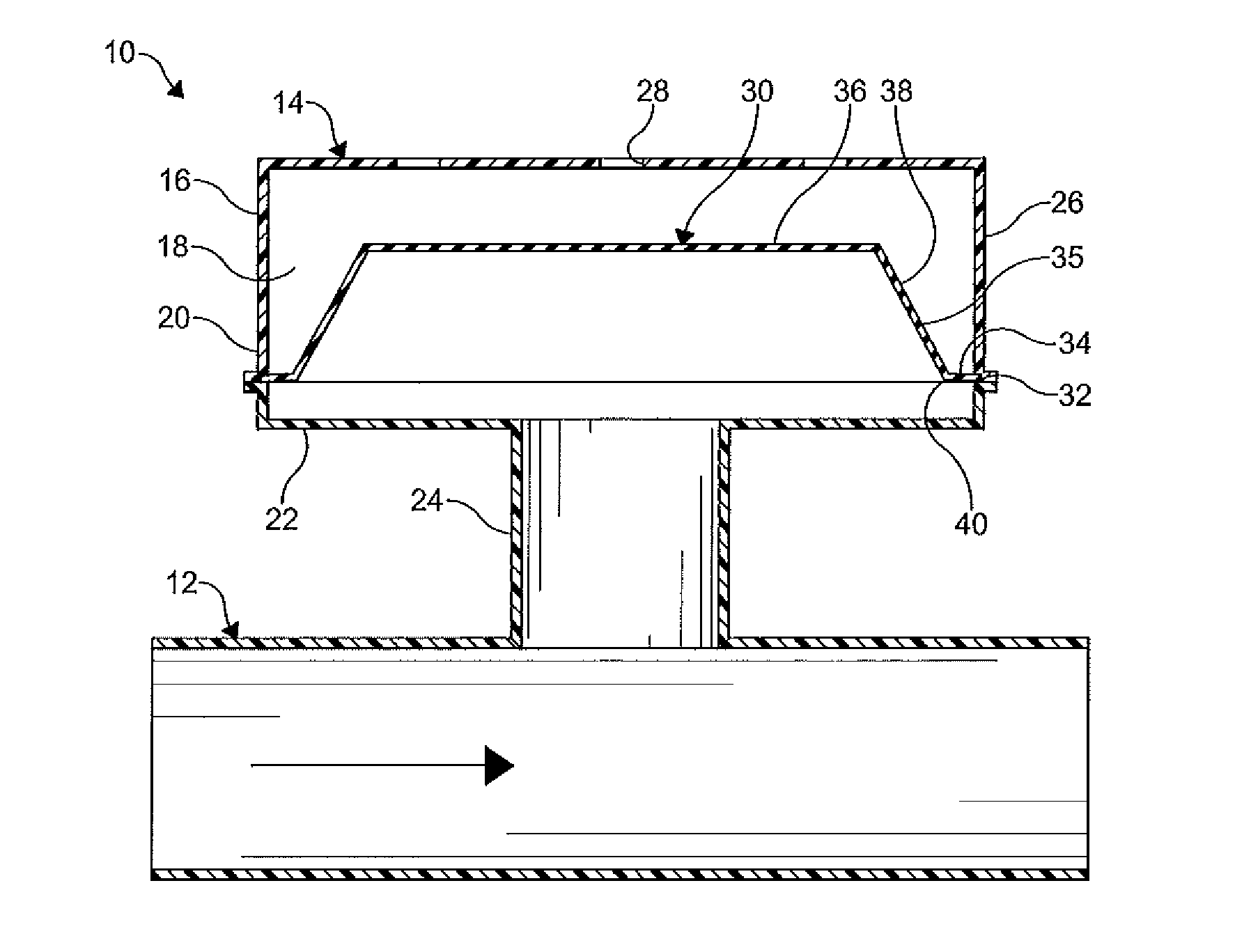
[0017]FIG. 1 shows a portion of an air flow system 10 according to an embodiment of the present invention. The air flow system 10 includes an air conduit 12 and a resonator 14. A first end of the air conduit is in fluid communication with an internal combustion engine (not shown) which is adapted to be disposed in an engine compartment of a motor vehicle. The air conduit 12 is in fluid communication with at least one of an air induction system and an air exhaust system. An air stream flows through the air conduit 12 as indicated by the directional arrow of FIG. 1 to the internal combustion engine. As is known in the art, the air induction system is typically adapted to deliver a stre...


PUM


Abstract

A resonator for a vehicle is provided, including a housing having at least one chamber formed therein. The housing has at least one aperture formed in a wall thereof. The housing is in fluid communication with an air conduit of the vehicle. At least one flexible member is disposed within the chamber of the housing. The flexible member includes an outer portion and an inner extension protruding from the outer portion which vibrates to attenuate low frequency sound energy transmitted from the air conduit.

Description

FIELD OF THE INVENTION[0001]The present invention relates generally to a resonator for an air flow system and, more particularly, to a compact low frequency resonator for an air flow system of a vehicle.BACKGROUND OF THE INVENTION[0002]An internal combustion engine in a vehicle typically is in fluid communication with an air induction system and an air exhaust system for providing air to the engine, and exhausting air from the engine, respectively. In the internal combustion engine, sound energy is often generated in the form of acoustic pressure waves as air flows through the air induction and exhaust systems. In particular, vibrations are often caused by intake air flowing through an air feed conduit of the air induction system. Specifically, vibrations are caused by the induction of air into a cylinder of the internal combustion engine by a cyclic movement of a piston slidably disposed in the cylinder.[0003]Generally, resonators are employed to reduce engine intake noise and impr...

Claims


Application Information

Patent Timeline
Patent Type & Authority Patents(United States)
IPC IPC(8): F01N1/02F01N1/16F01N1/08F01N13/08F02M35/00F02M35/10E04F17/04
CPCF02M35/1238F02M35/1266F02M35/1272F01N1/02G10K11/172F01N1/22F01N2490/14
Inventor HELLIE, MARK DONALDARRUDA, ANTHONY C.SHAW, CHRISTOPHER EDWARDSPARKS, JOSHUA
Owner HANON SYST
Why Eureka
Try Eureka