Optimized and miniaturized aerosol generator

a generator and aerosol technology, applied in the direction of instruments, heat measurement, computer control, etc., can solve the problems of the apparatus to shut down, achieve the effect of reducing the rate at which the ozone spontaneously decomposes, reducing the temperature of the inside of the enclosure, and improving the oxidation performan

Inactive Publication Date: 2013-02-26
ALTAPURE
View PDF27 Cites 64 Cited by
  • Summary
  • Abstract
  • Description
  • Claims
  • Application Information

AI Technical Summary

Benefits of technology

[0079]In the seventh part of this embodiment, the UV light source(s) can, without limitation, be combined with any aerosol or vapor generating apparatus that emits an aerosol or vapor containing one or more of, in any concentration, hydrogen peroxide, peroxyacetic acid (PAA), or any other aqueous solutions or agent(s) that are acidic, or any combinations thereof. This embodiment can also, without limitation, be combined with the use of a dehumidification technology. According to U.S. Pat. No. 7,045,096 B2 to D'Ottone, a high relative humidity (RH) increases the effectiveness of the invention as water droplets can deliver concentrated solutions of hydroxyl free radicals throughout the area in which it is employed ('096 patent, line 56). This effect can be, without limitation, enhanced in the present invention, as the dense cloud of very small aerosol droplets and vapor that is suspended in the air or gas in the treated area(s), is pulled into the enclosure or area that houses the UV light source(s) and is treated by the UV light and then deployed back into the treated area(s). This may, without limitation, be more enhanced when the aerosol or vapor droplets are less than ten (10) micron in size. This may, without limitation, be even more enhanced when the droplets are generated with ultrasonic processes, which are known to emit large amounts of aerosol droplets less than five (5) microns in diameter.
[0080]The use of any dehumidifier that is, without limitation, directly or indirectly connected to one or more UV light source(s) can also add an additional synergistic effect by reducing the relative humidity of the air or gas stream that is presented to the UV light source(s) after one or more passes of the same air or gas from the treated area(s). This may be beneficial as it may, without limitation, be possible to initially inundate the UV light source(s) with limiting conditions such as, but not limited to, too much humidity, or too much aerosol, which could wet the UV light source(s) under certain conditions known to those skilled in the art, and their performance or efficiency of the UV light source(s), such as in eliminating bacteria in the air or gas stream, could be decreased. In addition, according to U.S. Pat. No. 7,045,096 B2 to D'Ottone, to reduce the rate at which the ozone spontaneously decomposes into oxygen it is preferable, if possible, to lower the temperature of the inside of the enclosure ('096 patent, lines 48-51), where the UV light source(s) are located. The UV light source(s) can, without limitation, be located in close proximity to, in the same enclosure as, or effectively near, any chill coil(s), cooling tube(s), or cooling surface(s), associated with any dehumidifier designs known to those skilled in the art, to help reduce the temperature of the air or gas near the UV light source(s) to an effective temperature between 0-70 degree Centigrade, and more preferably near 0-15 degree Centigrade.
[0081]According to U.S. application Ser. No. 10 / 671,837 by Morneault et al, (paragraph 8), “A variation of photocatalytic oxidation, dubbed Advanced Photocatalytic Oxidation (APO) is defined by the complementary utilization of any ozone, hydrogen peroxide, or reactive material surfaces such as titanium dioxide in tandem with UV energy, and is deemed to yield higher oxidation performance, but it comes with the higher costs to operate and bulkiness to the apparatus.” This effect can also, without limitation, be enhanced in the present invention, as the aqueous aerosol or vapor, containing any amount of hydrogen peroxide or peroxyacetic acid (PAA), is pulled into the enclosure or area that houses the UV light source(s), from the treated area(s), and is treated by the UV light. The aqueous aerosol or vapor in the present invention is unique because it provides the benefit of inherently providing the needed substance(s) to yield higher oxidation performance without any additional cost, bulkiness, or complexity to the apparatus. This synergism may also, without limitation, be accomplished with any other aerosols consisting of any other agent(s) that can have the same or similar effect.
[0082]The combination of one or more of these various technologies such as, but not limited to, any enclosed UV light source(s), dehumidification, and any aqueous aerosol generator or vapor generator, technologies, especially when combined with the use of any aerosol containing any hydrogen peroxide and / or peroxyacetic acid (PAA), can without limitation, create an enhanced synergy that can be used for a quicker process to not only decontaminate, sanitize, disinfect, or sterilize, a targeted area and various surfaces within the targeted area, but to also quickly reduce or eliminate odors or smells in the targeted area that results from these activities. This can, without limitation, be especially important when using agent(s) that contain ingredients such as, but not limited to, peroxyacetic acid (PAA). This synergy, can also, without limitation, be even more enhanced when acidic agent(s) are deployed into a targeted area and treated by the UV light source(s). This can translate to quicker overall cycle or turn over times for a treated space.
[0083]An apparatus and method of an embodiment of the present invention, briefly summarized, comprises using any combination of sensors, programmable logic circuit (PLC), computer software, algorithms, or other automated means known to those skilled in the art, to automatically adjust and modify the timing sequences and time periods of various steps of the operational cycle performed by any aerosol generating apparatus or any ancillary equipment, at any time, to account for various attributes such as, but not limited to, the total volume of the treated space, temperature of the air or gas in the treated space, the relative humidity level in the treated space, the dew point in the treated space, and the atmospheric pressure in the treated space. In addition, the operator of the apparatus can, without limitation, manually enter into the apparatus one or more values such as, but not limited to, the volume of the room or treated space, or the desired operational time for any of the various steps of any operation cycle.
[0084]An apparatus and method of an embodiment of the present invention, briefly summarized, comprises the aerosol generator conducting or carrying out, without limitation, the following operational steps or sequences. One or more of the following steps can also, without limitation, be bypassed either temporarily or permanently per the desires or needs of the operator. Each step can vary for any length of time for any reason known to those skilled in the art. In addition the time between each step can also vary for any length of time for any reason. The first step is aerosol generation and deployment into the one or more targeted area(s). This step includes, without limitation, the additional step of heating the liquid that will be aerosolized to any preset temperature. The second step provides a dwell time to allow the aerosol and any vapor component to have efficacious contact with any targeted surfaces and / or area(s). The third step is dehumidification. Dehumidification can be achieved in various ways known to those skilled in the art. Dehumidification can also, without limitation, include operating any spinning paddles or blades as mentioned in the present invention, and this can be operated with our without any other dehumidification device(s) or methodologies. The fourth step is deodorization. This is achieved by using one or more UV light source(s) as described in the present invention. The fifth step is filtering the air with one or more of any filter(s) to remove any amount of any unwanted gases or vapor. Furthermore, the aerosol generating apparatus may stop all other steps and enter into or start the dehumidification step at any time for any reason. The dehumidification step may be started for reasons including, but not limited to, the apparatus or operator has detected a fault with any part or operation of the apparatus or any other ancillary equipment, an emergency stop has been actuated, or the operator has chosen to abort or stop the function of the apparatus. Finally, the operator of the apparatus can, without limitation, manually operate the dehumidification step or deodorization step either any time before the aerosol generating apparatus has started to generate and deploy any aerosol, or any time after the entire operational cycle is complete.

Problems solved by technology

The transducers are submerged in one or more tanks or reservoirs, and cause a surface disturbance, which results in the formation of an aerosol of the liquid in the tanks or reservoir(s).
The tanks or reservoirs also have a means to sense if they are under or overfilled, and can cause the apparatus to shut down if this occurs.

Method used


Image

  • Optimized and miniaturized aerosol generator
  • Optimized and miniaturized aerosol generator
  • Optimized and miniaturized aerosol generator

Examples


Embodiment Construction

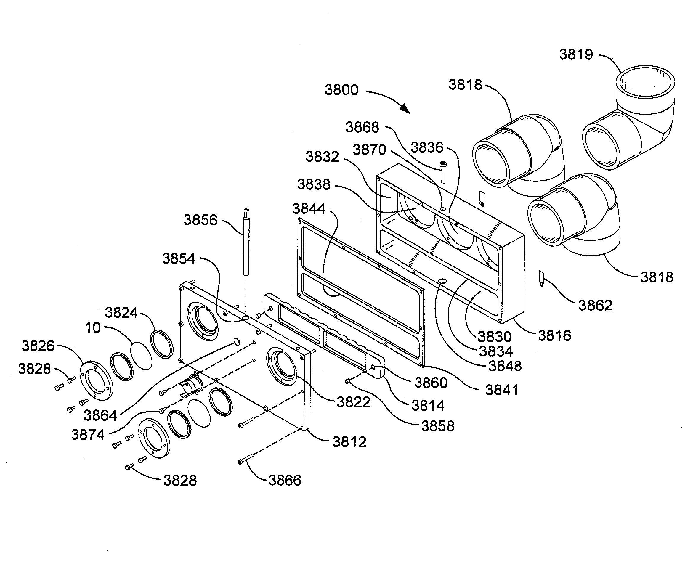
[0231]Detailed references to the embodiments of the invention, are illustrated in the accompanying drawings that serve as examples. While the invention will be described in conjunction with the embodiments, it is understood that they are not intended to limit the invention to those embodiments. On the contrary, the invention is intended to cover alternatives, modifications, and equivalents, which may be included within the spirit and scope of the invention as defined by the appended claims.

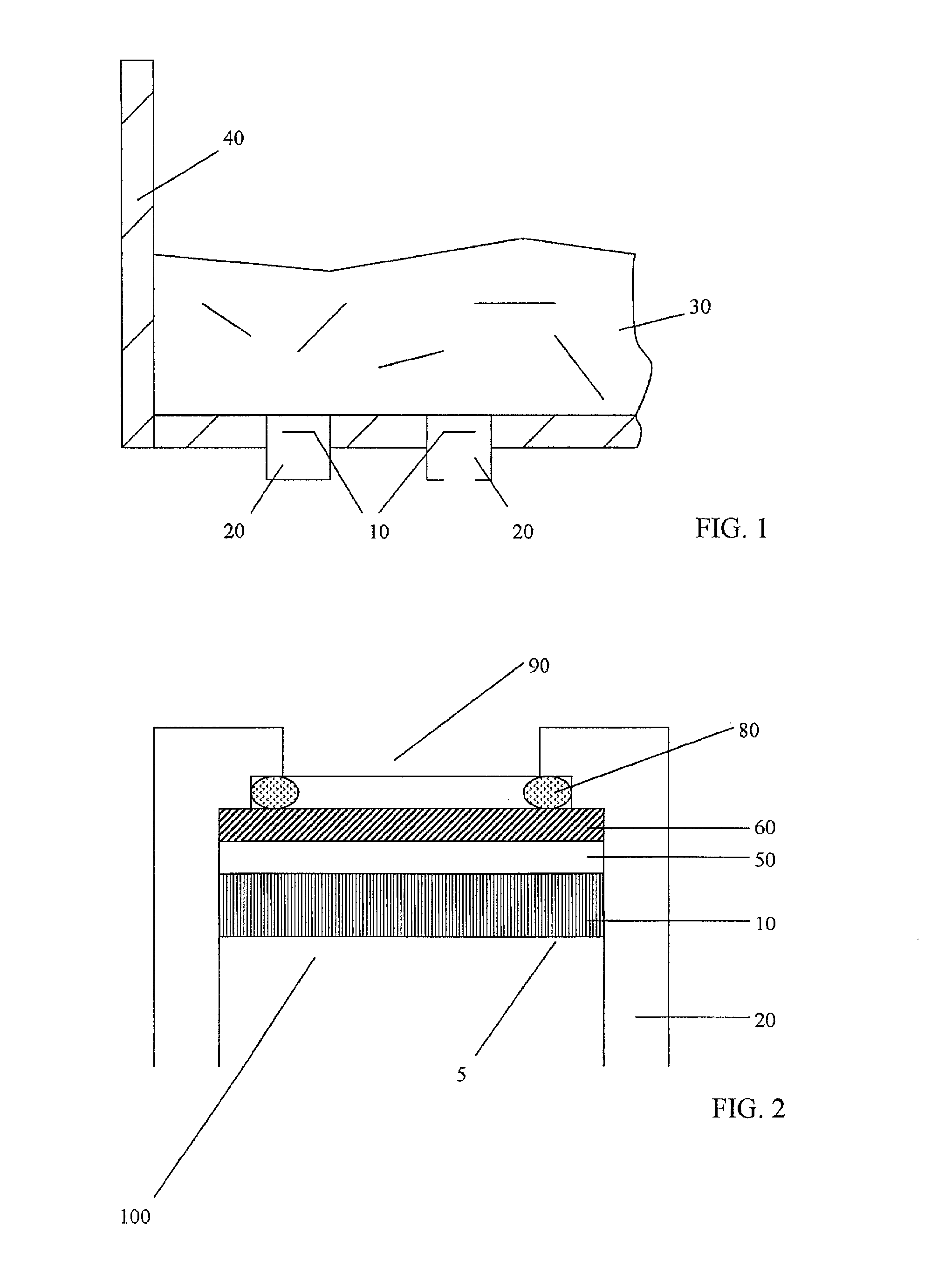
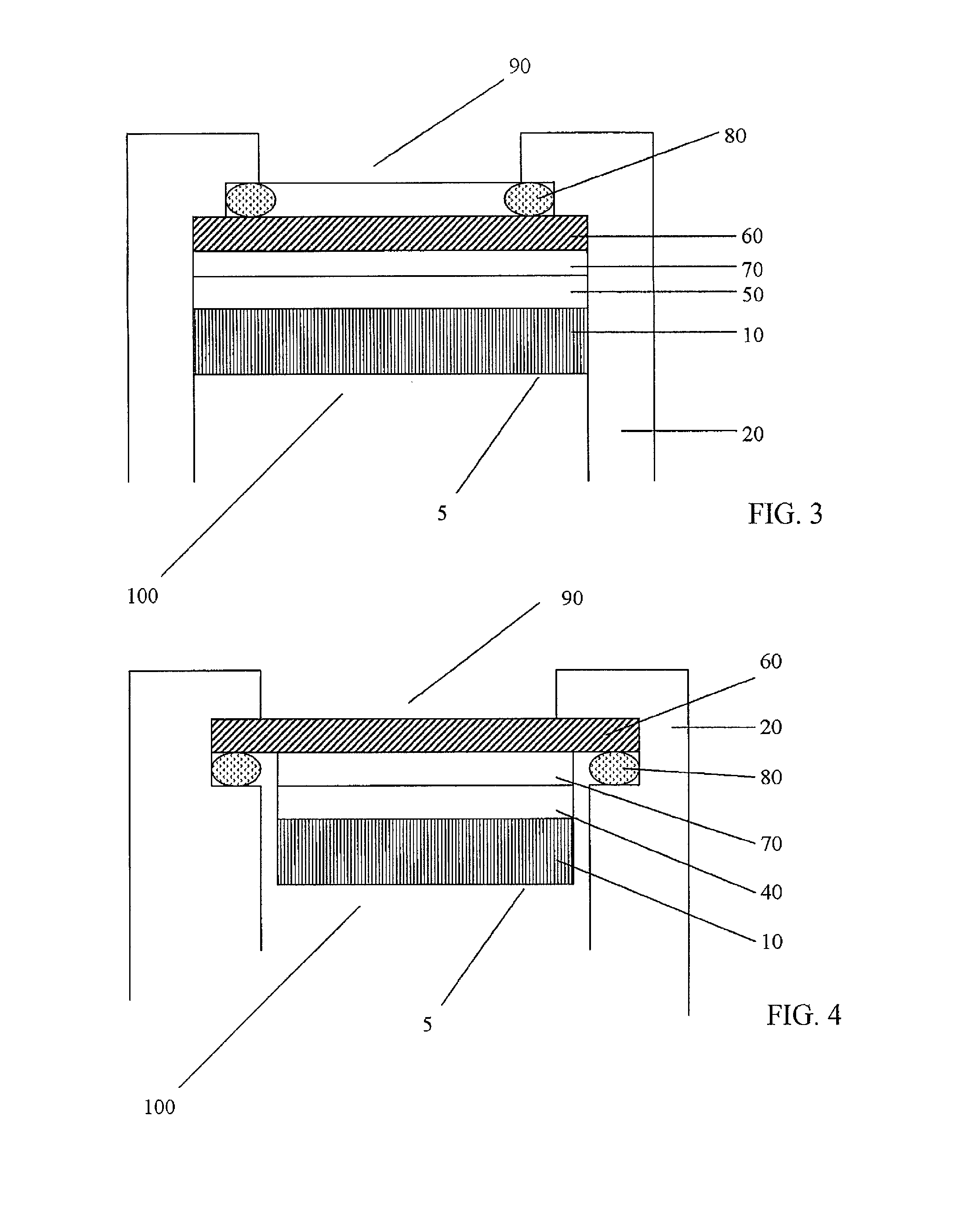
[0232]As illustrated in FIGS. 1-5B, an embodiment of the invention includes a method and apparatus for protecting and enhancing the performance of one or more aerosol generating ultrasonic transducer(s) (10) by adhering one or more protective barrier(s) (60) to a transducer(s) (10). Unless otherwise stated, adhering in this specification includes, but is not limited to adhering, coupling, gluing, attaching, cementing, cohering, fastening, pasting, depositing, applying, melting onto or melting toge...


PUM


Abstract

An optimized and miniaturized aerosol generator preferably includes a transducer plate, at least one transducer, a level float, a fluid container, at least one aerosol output member and an air input member. At least one transducer counterbore is formed in the transducer plate to retain the at least one transducer. The fluid container includes a float chamber and an aerosol chamber. The at least one aerosol output and the air input member are retained in a top of the aerosol chamber. A sealing gasket is preferably placed between a top of the transducer plate and a bottom of the fluid. The level float is contained in the float chamber. Air is pumped into the aerosol chamber through the air input member. A transducer driver powers the at least one transducer. The at least one transducer vibrates and produces an aerosol, which exits the at least one aerosol output member.

Description

CROSS-REFERENCE TO RELATED APPLICATIONS[0001]This continuation-in-part application claims priority from U.S. Non-provisional application Ser. No. 12 / 816,986, filed on Jun. 16, 2010 now U.S. Pat. No. 8,177,142, which claims priority from U.S. Provisional Application Ser. No. 61 / 295,869, filed Jan. 18, 2010, and as a continuation-in-part of U.S. Non-Provisional patent application Ser. No. 12 / 114,454, filed on May 2, 2008, now U.S. Pat. No. 7,871,016, which claims priority both from U.S. Provisional Patent Application Ser. No. 60 / 915,524, filed on May 2, 2007, and as a continuation-in-part from U.S. patent application Ser. No. 11 / 509,332, filed on Aug. 24, 2006, now U.S. Pat. No. 7,641,130, which claims priority from U.S. Provisional Patent Application Ser. No. 60 / 711,858, filed on Aug. 26, 2005 and all of the above patent documents are expressly incorporated herein by reference in their entirety.TECHNICAL FIELD OF THE INVENTION[0002]The present invention relates to improved apparatuse...

Claims


Application Information

Patent Timeline
Patent Type & Authority Patents(United States)
IPC IPC(8): B05B17/06B05B1/08
CPCA61L2/22A61L9/122A61L9/14B05B17/0615B05B7/0012G01F23/00G01K7/02G05B15/02G05D7/0629A61L2/24A61L2202/14A61L2202/15B05B17/0607G01F23/30
Inventor RICCIARDI, JONATHAN J.RICCIARDI, CARL L.WOLF, II, JOHN D.
Owner ALTAPURE
Why Eureka
Try Eureka