Hydraulic thruster for vessel

a technology for hydraulic thrusters and vessels, applied in special purpose vessels, motor-driven power plants, vessel construction, etc., can solve the problems of existing hydraulic marine thrusters that cannot extend and retract their propellers, lack of quick and easy means to add additional thrusters to the system, etc., to achieve cost savings, extend over, and add additional thruster power.

Active Publication Date: 2013-02-26
WILLIAMS JOHN T
View PDF20 Cites 2 Cited by
  • Summary
  • Abstract
  • Description
  • Claims
  • Application Information

AI Technical Summary

Benefits of technology

[0012]Accordingly, it is an object of the present invention to provide a hydraulic thruster for vessel which may be readily attached to an existing marine hydraulic thruster system. Design features allowing this object to be accomplished include a housing tiltably attached to a bracket, a cylinder rigidly attached to the housing, a tube slidably and rotatably attached to the cylinder, and means of removably attaching the bracket to a vessel deck. Advantages associated with the accomplishment of this object include flexibility in adding additional thruster power, and cost savings where unnecessary thruster power is not installed.
[0013]It is another object of the present invention to provide a hydraulic thruster for vessel which is capable of extending over a significantly greater range than currently available designs. Design features allowing this object to be accomplished include a tube reciprocating within a cylinder, and externally-mounted extension actuator(s) which provide a significantly greater extension / retraction range than currently available extension actuators. Benefits associated with the accomplishment of this object include flexibility of installation of the instant hydraulic thruster for vessel into vessels of greater than usual depth, and increased flexibility of use.
[0014]It is still another object of this invention to provide a hydraulic thruster for vessel which can fold into a compact size for shipping, without having to disassemble the thruster to reduce its shipping size. Design features enabling the accomplishment of this object include a housing tiltably attached to a bracket, a cylinder rigidly attached to the housing, a tube slidably and rotatably attached to the cylinder, and at least one tilt actuator disposed above the bracket, in order to provide a flat-profile for the hydraulic thruster for vessel when it is completely tilted up. Advantages associated with the realization of this object include reduced labor in preparing the hydraulic thruster for vessel for shipping, reduced setup cost after shipping, and reduced shipping cost due to smaller shipping volume.
[0015]It is another object of the present invention to provide a hydraulic thruster for vessel having positive, redundant down-stops to securely prevent over-tilting of a fully down-tilted thruster when it is developing forward thrust. Design features allowing this object to be accomplished include a housing which butts up against a pair of bracket-mounted stops when the hydraulic thruster for vessel cylinder and tube are tilted completely down, and at least one housing-mounted down-stop tab which butts against the bracket when the hydraulic thruster for vessel cylinder and tube are tilted completely down. Benefits associated with the accomplishment of this object include more stable and smoother thruster operation and steering.
[0016]It is still another object of this invention to provide a hydraulic thruster for vessel having means of securely and removably fastening a thruster to the deck of a vessel upon which it is mounted. Design features enabling the accomplishment of this object include at least one bracket floor brace having bracket floor brace bores sized to slidably admit a weld tab fastener, and a weld tab with a weld tab threaded bore sized to mate with the weld tab fastener. Advantages associated with the realization of this object is the ability to securely and removably bolt the hydraulic thruster for vessel to a deck to which weld tabs have been welded, and the associated flexibility of use.
[0017]It is yet another object of this invention to provide a hydraulic thruster for vessel which is economical to produce. Design features allowing this object to be achieved include the use of commercially available elements, and components made of readily available materials. Benefits associated with reaching this objective include reduced cost, and hence increased availability.

Problems solved by technology

One problem with existing marine thruster system designs is the absence of a quick and easy means to add additional thrusters to the system, as required.
In addition, there are a number of problems with existing marine hydraulic thrusters themselves.
One problem is that existing hydraulic marine thrusters can only extend and retract their propellers units around twenty inches.
Another problem with existing marine hydraulic thrusters is the challenge involved in shipping them.
Still another problem associated with currently-available marine thrusters is the absence of a secure down-stop when the thruster is tilted completely down.
Yet another problem associated with existing marine hydraulic thrusters is the absence of a means of securely fastening a thruster to the deck of a vessel upon which it is to be mounted, short of physically welding the thruster base directly to the vessel deck.

Method used


Image

  • Hydraulic thruster for vessel
  • Hydraulic thruster for vessel
  • Hydraulic thruster for vessel

Examples


Embodiment Construction

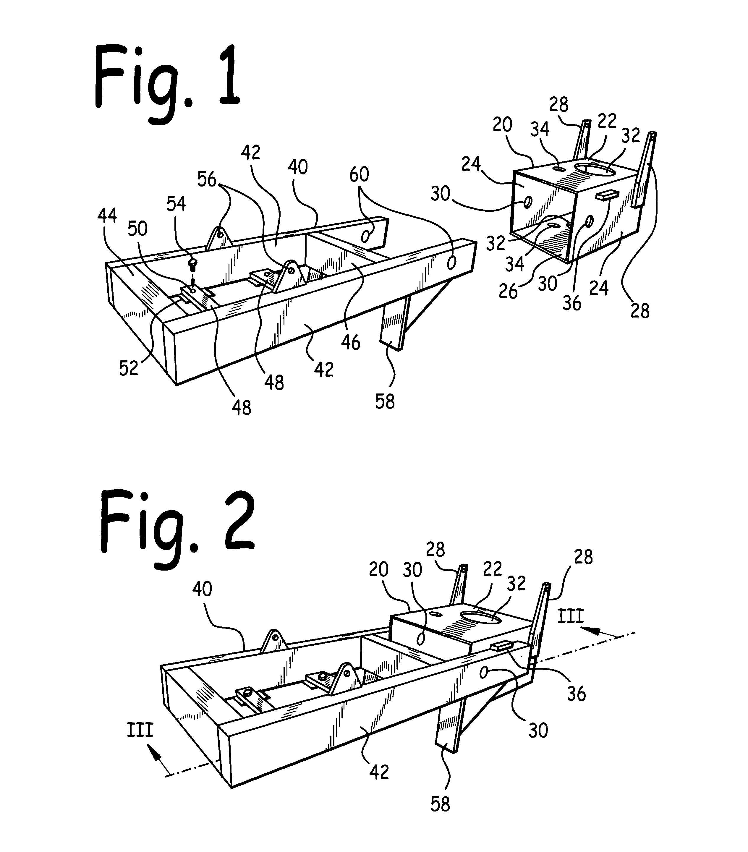
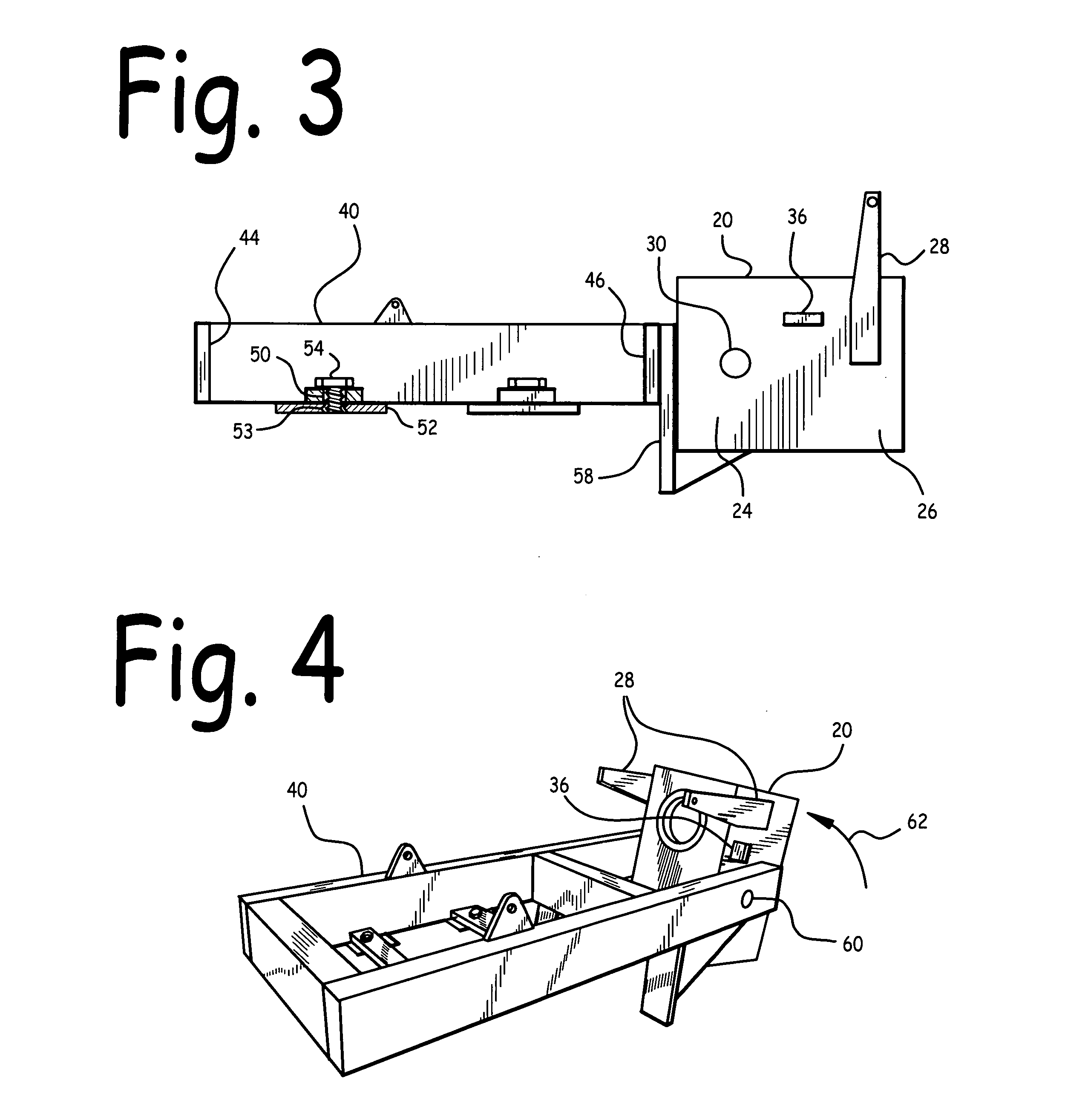
[0029]FIG. 1 is a left front elevated isometric view of bracket 40 and housing 20. FIG. 2 is a left front elevated isometric view of housing 20 tiltably attached to bracket 40, with housing 20 tilted down. FIG. 3 is a side cross-sectional view of housing 20 tiltably attached to bracket 40, with housing 20 tilted down, taken at section of FIG. 2. FIG. 4 is a left front elevated isometric view of housing 20 tiltably attached to bracket 40, with housing 20 tilted up.

[0030]Referring to FIGS. 1-4, housing 20 comprises housing roof 22 rigidly attached to a pair of housing sides 24, which in turn are rigidly attached to housing floor 26. The upper edge of a first housing side 24 is attached along one edge of housing roof 22; the upper edge of a second housing side 24 is attached along an edge of housing roof 22 opposite first housing side 24. The lower edge of first housing side 24 is attached along one edge of housing floor 26; the lower edge of second housing side 24 is attached along an...


PUM


Abstract

A hydraulic thruster for vessel. The hydraulic thruster is intended for incorporation into a modular vessel thruster system, and is easily installed onto, and removed from, a vessel having such system. A housing is tiltably attached to a bracket, which in turn is removably mounted to a vessel. A cylinder is rigidly attached to the housing, and a tube is extensibly and rotatably disposed within the cylinder. A thrust means is disposed at a lower end of the tube. The instant thruster incorporates positive redundant down-tilt stop means, increased extension/retraction range, reduced shipping size, and means for securely and removably attaching the thruster to a vehicle deck.

Description

CLAIM FOR PRIORITY[0001]This utility patent application is a Continuation-In-Part U.S. utility application Ser. No. 12 / 800,026 filed May 6, 2010 entitled Modular Hydraulic Thruster System for Vessel, which is a Continuation-In-Part of U.S. utility application Ser. No. 12 / 381,245 filed Mar. 10, 2009 now U.S. Pat. No. 7,883,384 entitled Self-Contained Hydraulic Thruster for Vessel, which is a Continuation-In-Part of U.S. utility application Serl. No. 11 / 999,531 filed Dec. 6, 2007 now U.S. Pat. No. 7,654,875 entitled Self-Contained Hydraulic Thruster for Vessel, which was based upon U.S. provisional patent application Serl. No. 60 / 903,400 filed Feb. 26, 2007 entitled Self-Contained Hydraulic Thruster for Vessel; and claims the benefit of the earlier filing date of these applications.BACKGROUND OF THE INVENTION[0002]1. Field of the Invention[0003]This invention relates to vessel propulsion systems, and in particular to a hydraulic thruster for vessel.[0004]2. Background of the Invention...

Claims


Application Information

Patent Timeline
Patent Type & Authority Patents(United States)
IPC IPC(8): B63H21/12
CPCB63H23/26B63H25/42B63H5/125
Inventor WILLIAMS, JOHN T.
Owner WILLIAMS JOHN T
Why Eureka
Try Eureka