MS/MS mass spectrometer

a mass spectrometer and mass spectrometer technology, applied in the direction of electron/ion optical arrangement, particle separator tube details, separation process, etc., can solve the problems of deteriorating the quality of the quantitative measurement of the objective component, power supply circuit with a rather complex configuration, etc., to achieve the reduction of noise that appears in the ms/ms spectrum, improve the accuracy of quantitative and qualitative analyses, and high the effect of removing

Active Publication Date: 2013-02-26
SHIMADZU CORP
View PDF16 Cites 5 Cited by
  • Summary
  • Abstract
  • Description
  • Claims
  • Application Information

AI Technical Summary

Benefits of technology

[0035]By the MS / MS mass spectrometer according to the present invention, the ions remaining in the collision cell (i.e. the previous precursor ion and the product ions generated from this precursor ion) can be quickly removed from the collision cell at an appropriate timing, e.g. when the precursor ion is changed. As a result, the noise that appears in the MS / MS spectrum will be reduced, so that the accuracy of the quantitative and qualitative analyses will be improved. Particularly, the MS / MS mass spectrometer according to the present invention can achieve a high level of ion-removing effect at low cost. This is due to the use of a pulsed DC voltage applied to the lens electrodes to which no radio-frequency voltage with large amplitude is applied. The DC voltage creates a DC electric field having an ion-removing capability. The pulsed voltage can be applied without using a complex power supply circuit.
[0036]In the case where the residual ions within the collision cell are removed by being pulled toward the lens electrodes, the neutralized molecules adhere to one or both of the entrance and exit lens electrodes, while the adhesion of ions to the ion guide provided in the collision cell is avoided. Normally, it is only a DC bias voltage that is applied to the lens electrodes during the analysis, and the surface contamination of these lens electrodes has merely minor impacts on the analysis. Thus, it can be said that the present system is highly resistant to contamination. The lens electrodes can be more easily cleaned than the ion guide, which is contained within the collision cell. When a lens electrode is contaminated and needs to be cleaned, the cleaning work can be quickly completed with little effort.

Problems solved by technology

The crosstalk may deteriorate the quality of the quantitative measurement of the objective component.
However, the radio-frequency voltage applied to the quadrupole is normally as high as a kV-order amplitude; applying a pulsed voltage instead of this high radio-frequency voltage requires a power supply circuit with a rather complex configuration.

Method used


Image

  • MS/MS mass spectrometer
  • MS/MS mass spectrometer
  • MS/MS mass spectrometer

Examples


first embodiment

[0070]One embodiment (first embodiment) of the MS / MS mass spectrometer according to the present invention is hereinafter described with reference to the attached drawings.

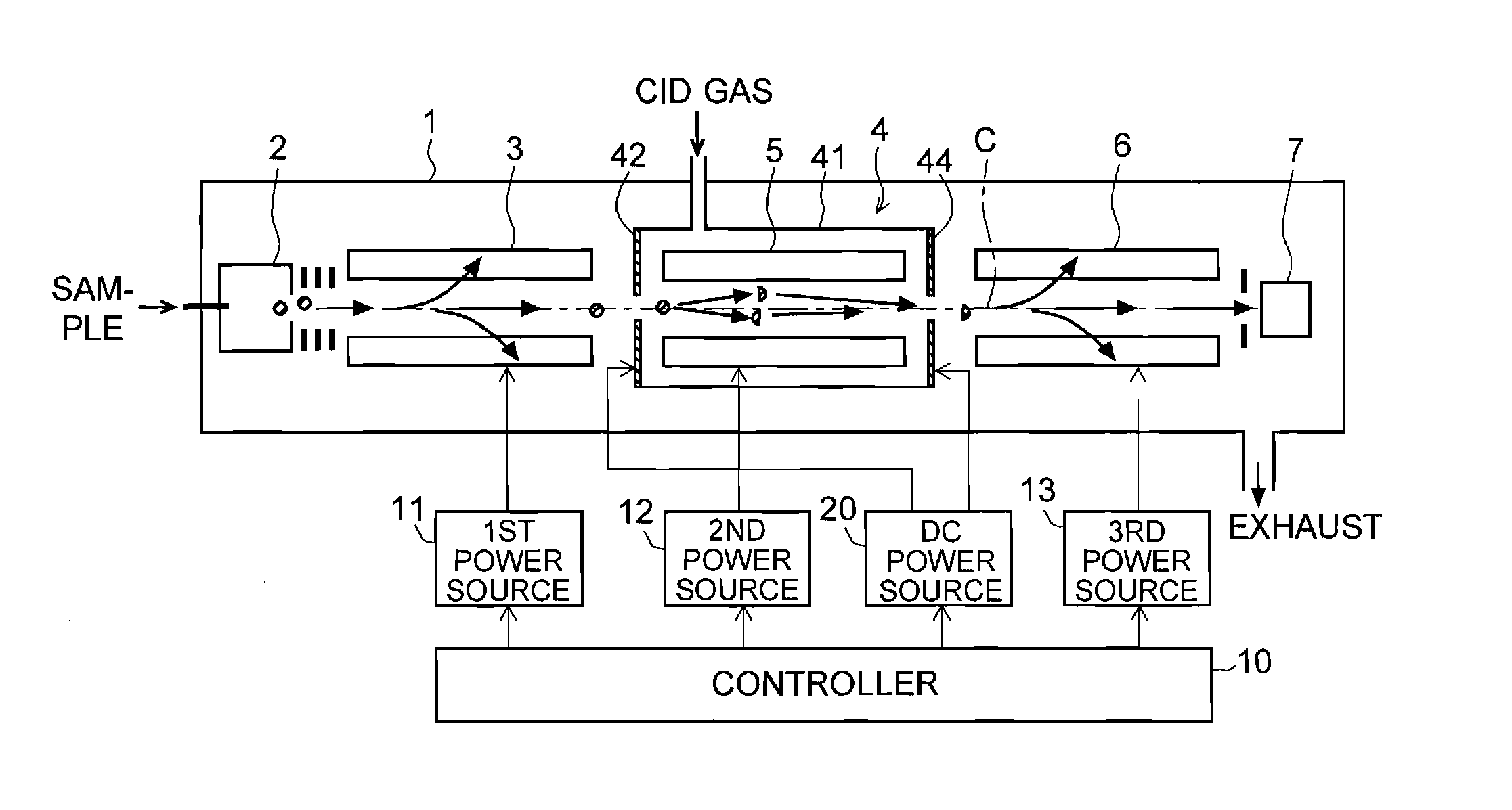
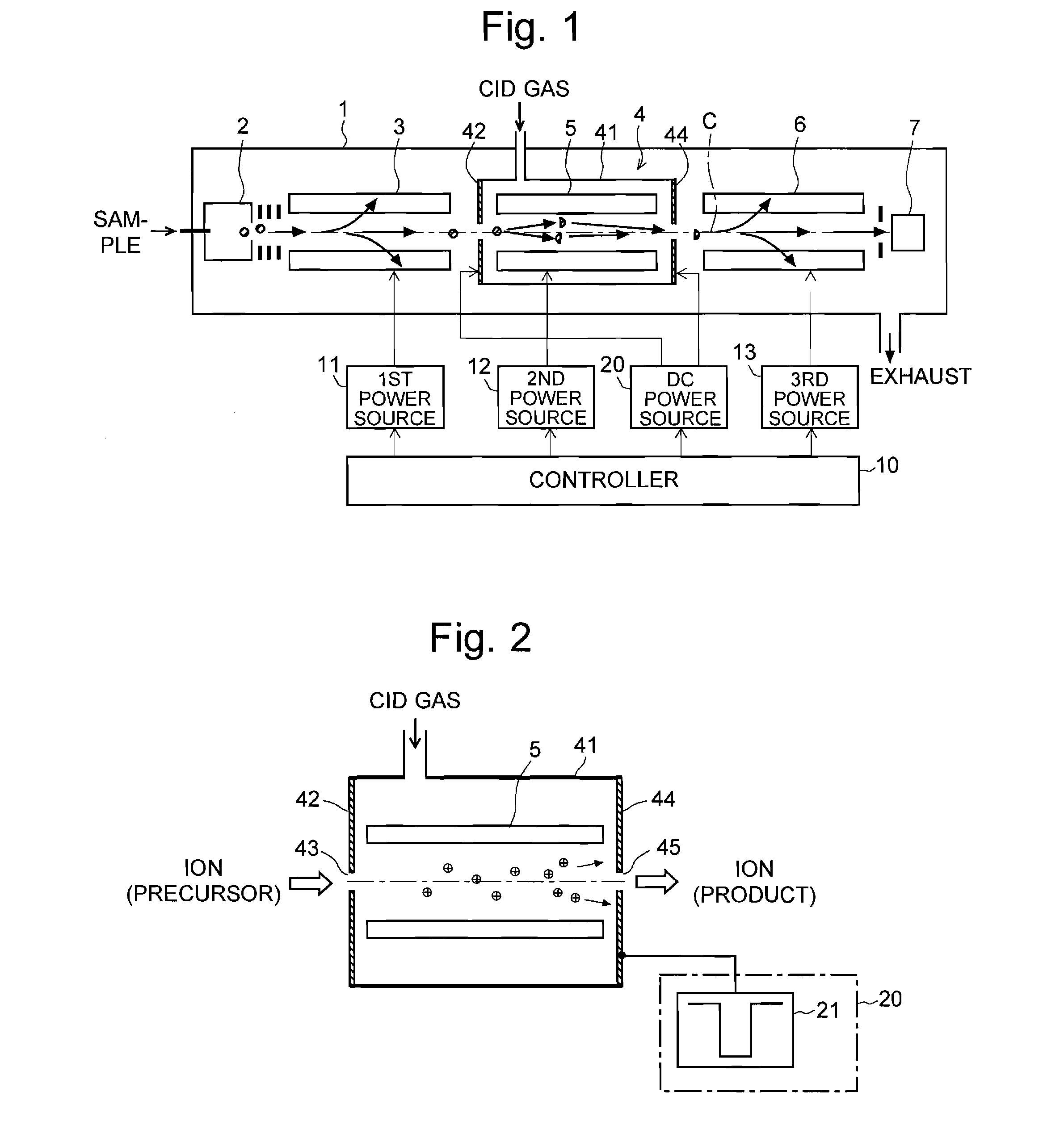
[0071]FIG. 1 is an overall configuration diagram of the MS / MS mass spectrometer of the first embodiment. FIG. 2 is a schematic configuration diagram of the collision cell 4 in FIG. 1 and its control-system circuit. The same components as used in the previously described conventional configuration are denoted by the same numerals and will not be specifically described.

[0072]Similar to the conventional case, the MS / MS mass spectrometer of the present embodiment has a first-stage quadrupole 3 (which corresponds to the first mass separator of the present invention) and a third-stage quadrupole 6 (which corresponds to the second mass separator of the present invention), between which a collision cell 4 for dissociating a precursor ion to produce various kinds of product ions is located, and a second-stage quadrupole 5 s...

second embodiment

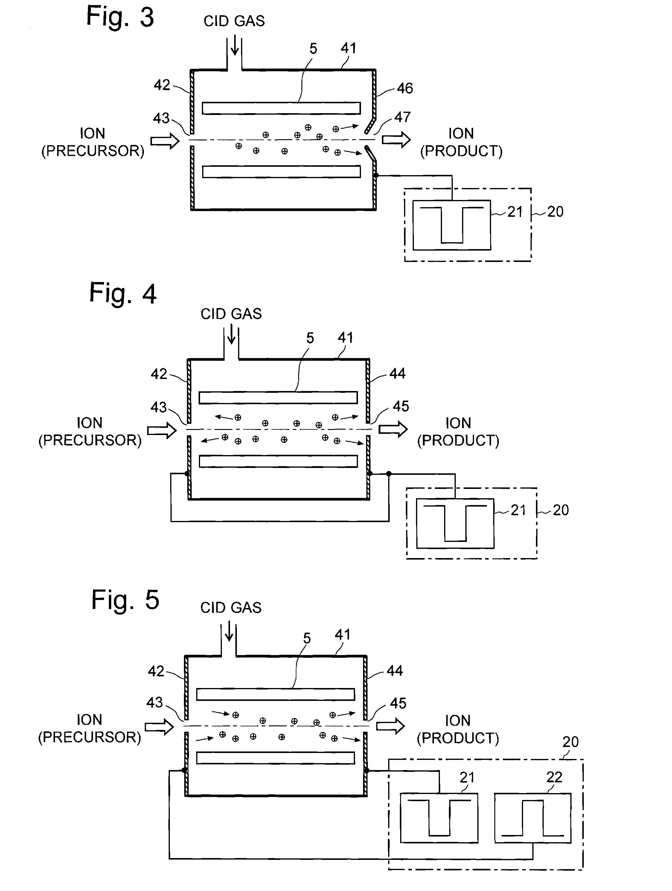
[0081]FIG. 3 is a schematic configuration diagram of the collision cell 4 and its power supply system in the MS / MS mass spectrometer of the second embodiment. In the MS / MS mass spectrometer of the second embodiment, the portion surrounding the aperture 47 of the exit lens electrode 46, to which a negative pulsed voltage is applied, is shaped like a skimmer protruding into the inner space of the collision cell 4. This structure strengthens the ion-pulling DC electric field created in the collision cell 4, so that the ions can be more easily accelerated. Particularly, even if the space surrounded by the second-stage quadrupole 5 is narrow, the effect of the DC electric field can spread over the entire space. This is effective in quickly removing the ions from the collision cell 4.

third embodiment

[0082]FIG. 4 is a schematic configuration diagram of the collision cell 4 and its power supply system in the MS / MS mass spectrometer of the third embodiment. In the MS / MS mass spectrometer of the third embodiment, the same pulsed voltage is applied to both the entrance lens electrode 42 and the exit lens electrode 44. Each of the residual ions within the collision cell 4 is pulled to either the entrance lens electrode 42 or the exit lens electrode 44 and normally to the closer one. Therefore, even an ion existing at positions close to the entrance lens electrode 42 in the collision cell 4 experiences an adequately strong force from the DC electric field. Furthermore, since the distances that the ions need to move to reach the lens electrodes 42 and 44 are short, the residual ions can be more quickly removed from the inner space of the collision cell 4.


PUM


Abstract

During a halt period of time when the introduction of ions is temporarily discontinued to change an objective ion to be selected by a first mass separator in the previous stage, a pulsed voltage having a polarity opposite to that of the ions remaining in a collision cell (4) is applied to an entrance lens electrode (42) and exit lens electrode (44). The ions are pulled by the DC electric field created by this voltage, to be neutralized and removed by colliding with the lens electrodes (42, 44). Thus, the residual ions, which may cause a crosstalk, can be quickly removed from the inner space of the collision cell (4) without contaminating an ion guide (5) to which a radio-frequency is applied. Since no radio-frequency voltage is applied to the lens electrodes (42, 44), the circuit for applying the pulsed voltage can have a simple configuration. Thus, the cost increase is suppressed.

Description

TECHNICAL FIELD[0001]The present invention relates to an MS / MS mass spectrometer for performing a mass analysis of product ions (fragment ions) generated by dissociating an ion having a specific mass (or mass-to-charge ratio, to be exact) by collision-induced dissociation (CID).BACKGROUND ART[0002]An MS / MS mass analysis (or tandem analysis) is known as one of the mass spectrometric methods for identifying a substance with a large molecular weight and for analyzing its structure. A triple quadrupole (TQ) mass spectrometer is a typical MS / MS mass spectrometer. FIG. 11 is a schematic configuration diagram of a generally used triple quadrupole mass spectrometer disclosed in Patent Document 1 or other documents.[0003]This mass spectrometer has an analysis chamber 1 evacuated by a vacuum pump (not shown). This chamber contains an ion source 2 for ionizing a sample to be analyzed, three quadrupoles 3, 5 and 6, each including four rod electrodes, and a detector 7 for detecting ions and prod...

Claims


Application Information

Patent Timeline
Patent Type & Authority Patents(United States)
IPC IPC(8): H01J49/06
CPCH01J49/0045
Inventor FUJITA, SHINJIROOKUMURA, DAISUKEITOI, HIROTO
Owner SHIMADZU CORP
Why Eureka
Try Eureka