Wideband Doherty amplifier circuit with impedance combiner

a doherty amplifier and combiner technology, applied in amplifiers, amplifiers with semiconductor devices/discharge tubes, amplifiers, etc., can solve the problems of narrow amplifiers, inability to achieve high-asymmetric ratio between main and peak amplifiers, and inherent degradation of peak efficiency of doherty architecture, etc., to achieve constant power versus frequency and constant efficiency

Active Publication Date: 2013-02-26
WOLFSPEED INC
View PDF3 Cites 7 Cited by
  • Summary
  • Abstract
  • Description
  • Claims
  • Application Information

AI Technical Summary

Benefits of technology

[0005]Embodiments described herein employ a constant impedance combiner having a characteristic impedance equal to the required load modulated high impedance state of the main amplifier in a three way wideband Doherty amplifier circuit when the first and second peaking amplifiers are turned off. In this most narrow band case there is minimal band limiting presented to the main amplifier. A significant amount of band limiting is removed from the main amplifier path when running in the back off power region, yielding more constant power versus frequency and more constant efficiency versus frequency at a fixed back off power level. The amplifier embodiments described herein are well suited for wider band applications such that one amplifier circuit can simultaneously cover two or more adjacent bands of operation or be more consistent across a complete band of operation than currently existing architectures.

Problems solved by technology

However, if high efficiency at a high output backoff (OBO) is required, a highly asymmetric ratio between the main and peaking amplifiers is required.
The Doherty architecture has an inherent degradation in the efficiency between the peak OBO point and the peak power point.
This can lead to the amplifier being narrow band in nature due to the band-limiting characteristics of the ¼λ transmission lines.

Method used


Image

  • Wideband Doherty amplifier circuit with impedance combiner
  • Wideband Doherty amplifier circuit with impedance combiner
  • Wideband Doherty amplifier circuit with impedance combiner

Examples


Embodiment Construction

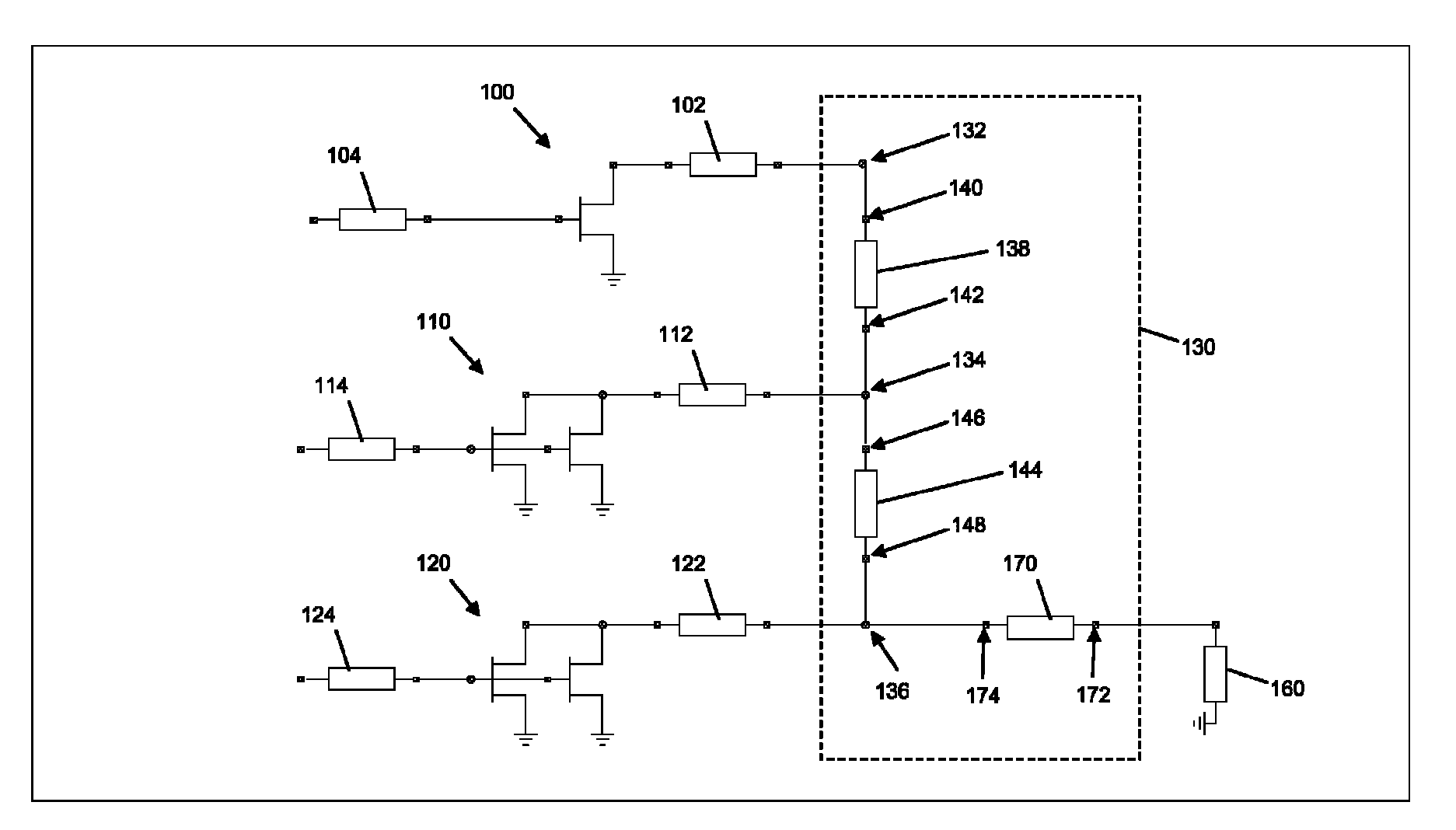
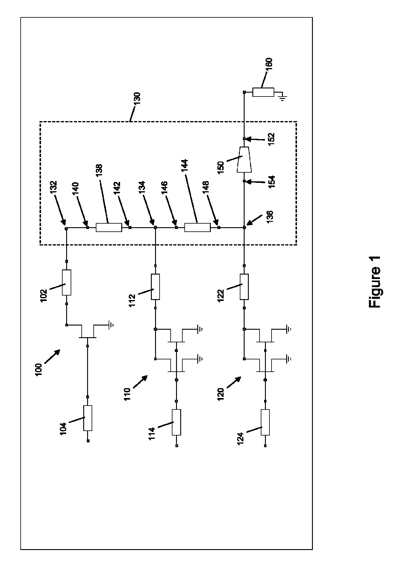
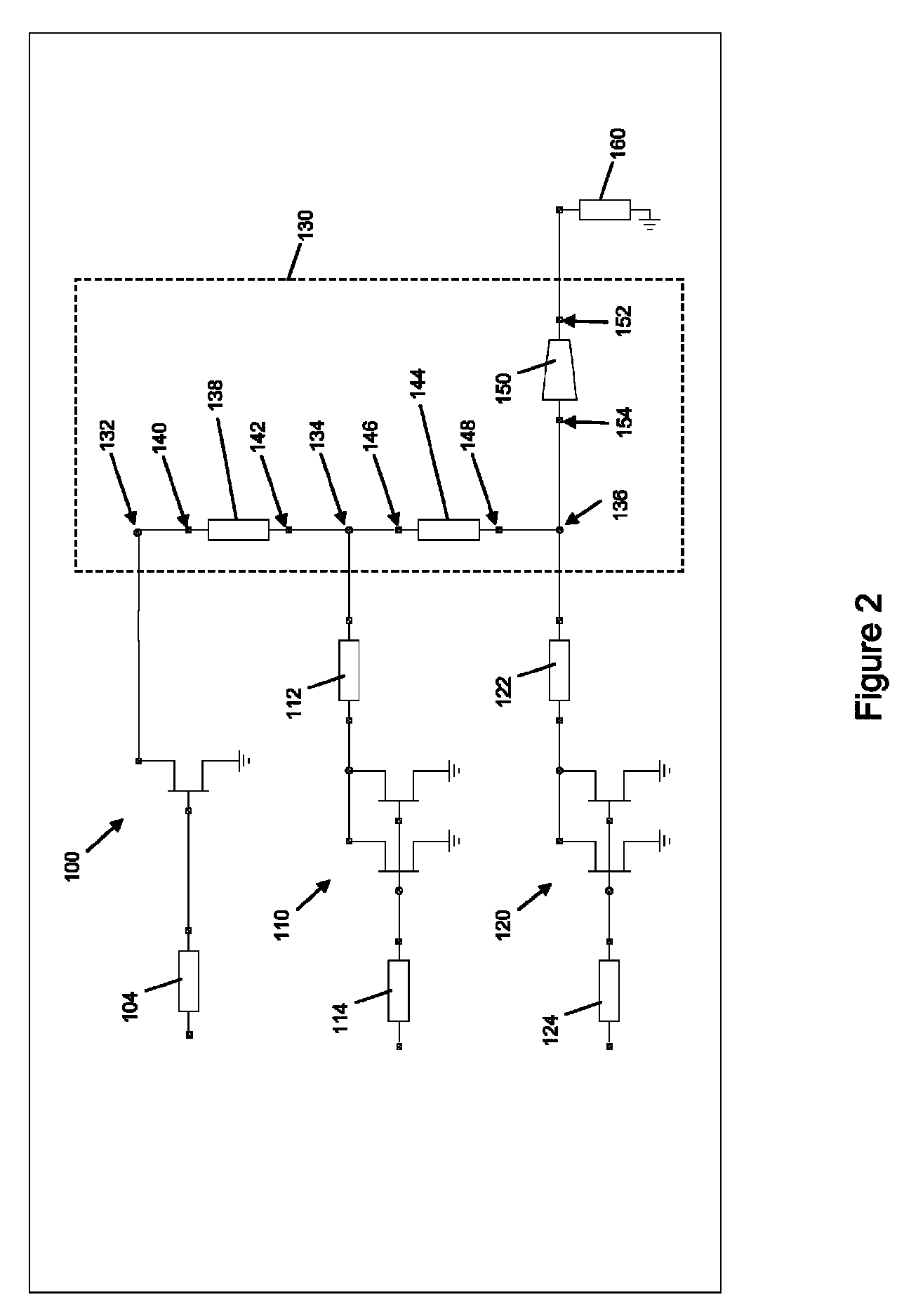
[0018]FIG. 1 illustrates an embodiment of a three way wideband Doherty amplifier circuit which includes a main amplifier 100 biased at Class B or AB mode, a first peaking amplifier 110 biased at Class C mode, a second peaking amplifier 120 biased at Class C mode, and a constant impedance combiner 130. Each amplifier 100, 110, 120 includes one or more active devices and may also include a respective output matching device 102, 112, 122. At low power levels, only the main amplifier 100 is operational. The efficiency of the main amplifier 100 increases as the power level increases. The main amplifier 100 eventually reaches a maximum efficiency point as the power level continues to rise. At this power level, the first peaking amplifier 110 turns on. The efficiency of the first peaking amplifier 110 similarly increases for power levels above this point. A second maximum efficiency point is attained when the first peaking amplifier 110 reaches its maximum efficiency point, at which point ...


PUM


Abstract

An amplifier circuit includes a first amplifier operable to turn on at a first power level, a second amplifier operable to turn on at a second power level below the first power level and a third amplifier operable to turn on at all power levels. A first power combiner is operable to combine an output of the third amplifier with an output of the second amplifier at a first power combining node to form a first combined amplifier output. A second power combiner is operable to combine the first combined amplifier output with an output of the first amplifier at a second power combining node to form a second combined amplifier output. An impedance transformer is operable to transform a load impedance of the amplifier circuit to a transformed impedance at the second power combining node, the transformed impedance matching an impedance of the first and second power combiners.

Description

PRIORITY CLAIM[0001]This application is a Divisional of U.S. application Ser. No. 13 / 163,388, filed on Jun. 17, 2011, the content of said application incorporated herein by reference in its entirety.FIELD OF TECHNOLOGY[0002]The present application relates to Doherty amplifiers, in particular Doherty amplifiers designed for a wideband frequency range of operation.BACKGROUND[0003]RF (radio frequency) power architectures within the telecommunications field focus on achieving high DC-to-RF efficiency at significant power back off from Psat (the average output power when the amplifier is driven deep into saturation). This is due to the high peak to average ratio (PAR) of the transmitted digital signals such as W-CDMA (wideband code division multiple access), LTE (long term evolution) and WiMAX (worldwide interoperability for microwave access). The most popular power amplifier architecture currently employed is the Doherty amplifier. The Doherty amplifier employs a class AB main amplifier...

Claims


Application Information

Patent Timeline
Patent Type & Authority Patents(United States)
IPC IPC(8): H03F3/68
CPCH03F1/0277H03F1/56H03F3/604H03F2200/318H03F2200/387H03F1/0288H03F2200/408
Inventor WILSON, RICHARDGOEL, SAURABH
Owner WOLFSPEED INC
Why Eureka
Try Eureka