Capacitively loaded spurline filter

a spurline filter and capacitor technology, applied in the direction of resonators, electrical equipment, waveguides, etc., can solve the problem and achieve the effect of reducing the layout area and enhancing the coupling

Active Publication Date: 2013-02-26
VIASAT INC
View PDF10 Cites 2 Cited by
  • Summary
  • Abstract
  • Description
  • Claims
  • Application Information

AI Technical Summary

Benefits of technology

[0005]In accordance with various aspects of the present invention, a system for a capacitively loaded spurline filter is presented. In an exemplary embodiment, a spurline filter is configured with capacitive elements, which facilitate a reduction in filter size while providing the same filtering performance in comparison to typical spurline filters that do not have capacitive elements. In one exemplary embodiment, implementation of capacitive elements reduces the spurline filter size by about 50% of the layout area while maintaining performance.
[0007]In another exemplary embodiment, a dual spurline filter comprises a through-line, a first spur and a second spur coupled to the through-line. A first capacitive element connects the through-line and the first spur, while a second capacitive element connects the through-line and the second spur. Similarly to the single spurline filter, the capacitive elements enhance the coupling effect and result in a decreased layout area.

Problems solved by technology

Similarly to the single spurline filter, the capacitive elements enhance the coupling effect and result in a decreased layout area.

Method used


Image

  • Capacitively loaded spurline filter
  • Capacitively loaded spurline filter
  • Capacitively loaded spurline filter

Examples


Embodiment Construction

[0016]While exemplary embodiments are described herein in sufficient detail to enable those skilled in the art to practice the invention, it should be understood that other embodiments may be realized and that logical electrical and mechanical changes may be made without departing from the spirit and scope of the invention. Thus, the following detailed description is presented for purposes of illustration only.

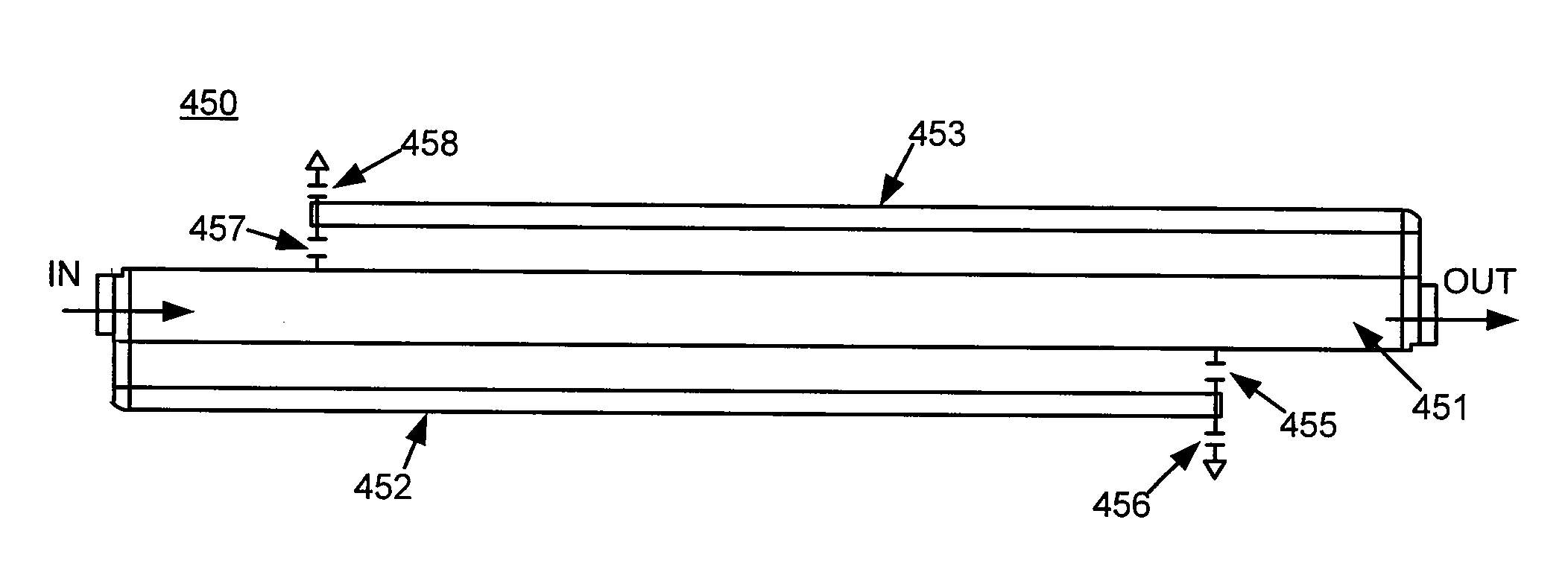
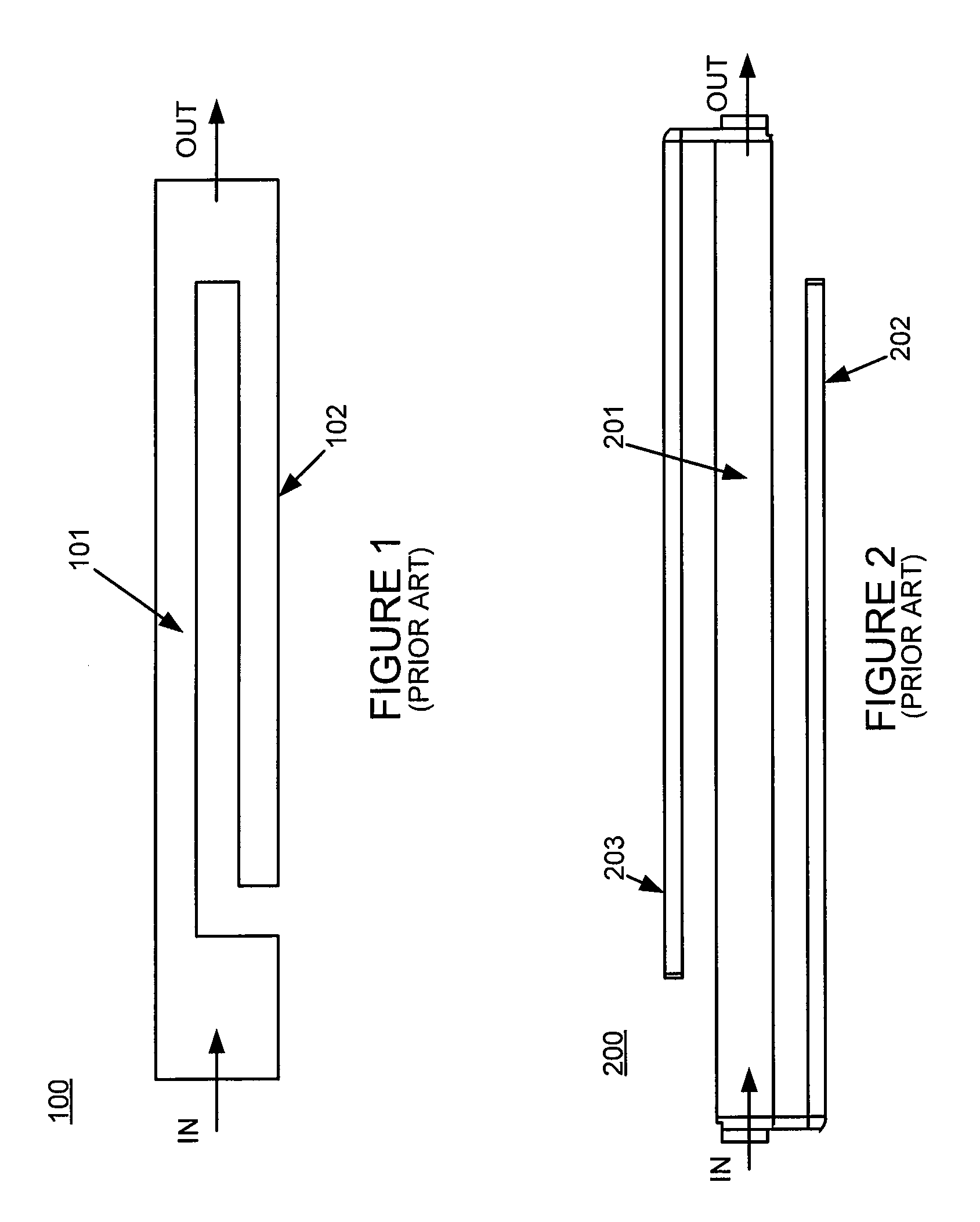
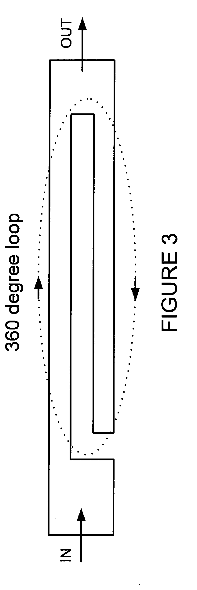
[0017]In an exemplary embodiment, a single-resonator spurline filter may be viewed as a 360° resonant loop, as illustrated in FIG. 3. The length of a conventional single-resonator spur line is a quarter of the signal wavelength (λ / 4). An input signal with a normalized phase of 0° travels down the through-line and then back up through the spur. When the signal has reached the open end of the spur, it has traveled λ / 2 and has a phase of 180°. The signal at the end of the spur and the input signal are now 180° out of phase, which is conducive to odd-mode coupling. Thus the 360° l...


PUM


Abstract

In an exemplary embodiment, a spurline filter comprises a capacitive element connected to a spur and either a through-line of the spurline filter or ground. In another embodiment, multiple capacitive elements are connected to the spur. In an exemplary embodiment, the capacitively loaded spurline filter provides a band rejection frequency response similar to the band rejection frequency response of a similar spurline filter that does not comprise at least one capacitive element but the capacitively loaded spurline filter has half the layout area or less. In an exemplary embodiment, the spurline filter comprises capacitive elements, where the capacitive elements are configured to reduce the resonant frequency of the filter.

Description

CROSS-REFERENCE TO RELATED APPLICATIONS[0001]This application is a non-provisional of and claims priority to U.S. Provisional Patent Application No. 61 / 112,613, entitled “CAPACITIVELY LOADED SPURLINE FILTER” and filed Nov. 7, 2008, which is hereby incorporated by reference.FIELD OF INVENTION[0002]The application relates to systems, devices, and methods related to a capacitively loaded spurline filter.BACKGROUND OF THE INVENTION[0003]A spurline filter is an effective band rejection filter. With reference to prior art FIG. 1, a layout of a prior art single-resonator spurline filter 100 includes a through-line 101 of the filter and a single spur 102. The single-resonator spurline filter 100 provides a band rejection notch at a resonant frequency of an incident signal. Similarly, FIG. 2 illustrates a dual-resonator spurline filter 200 comprising a through-line 201 of the filter, a first spur 202, and a second spur 203. In general, a dual-resonator spurline filter provides a wider band f...

Claims


Application Information

Patent Timeline
Patent Type & Authority Patents(United States)
IPC IPC(8): H01P1/203H01P7/08
CPCH01P1/20381H01P7/082
Inventor GRONDAHL, CHRISTOPHER D.LYONS, MICHAEL R.COOK, DEAN LAWRENCE
Owner VIASAT INC
Why Eureka
Try Eureka