Vehicle frame structure

a frame structure and vehicle technology, applied in the direction of roofs, electric propulsion mounting, jet propulsion mounting, etc., can solve the problem of difficult to distribute the front impact load over a wide area of the vehicle fram

Inactive Publication Date: 2013-03-12
TOYOTA JIDOSHA KK
View PDF15 Cites 29 Cited by
  • Summary
  • Abstract
  • Description
  • Claims
  • Application Information

AI Technical Summary

Benefits of technology

[0007]This invention thus provides a vehicle frame structure that is able to be made lighter while ensuring the ability to absorb shock during a frontal collision of a vehicle.
[0009]With the vehicle frame structure according to this aspect, each of the side members branches off in a direction toward the rear of the vehicle from the front side member at the front of the vehicle into the inner member which is toward the inside in the vehicle width direction and the outer member which is toward the outside in the vehicle width direction. Accordingly, the front impact load input to the side members (i.e., the front side members) during a frontal collision of the vehicle is distributed and transmitted to the inner members and the outer members. Also, the inner members extend toward the rear of the vehicle along the tunnel portion of the floor, so the front impact load is also transmitted toward the rear of the vehicle along this tunnel portion. Further, the inner members are connected together at a plurality of connecting portions in the longitudinal direction of the vehicle at least at a location corresponding to the front portion side of the tunnel portion. These connecting portions are designed to break when a front impact load is input to the one or both side members. Having the connecting portions break from the front impact load in this way enables the side members to deform not only at the area of the front side members, but also the area of the inner members which are located at the front portion of the tunnel portion. As a result, the shock during a frontal collision is able to be better absorbed. Accordingly, localized deformation of the floor is able to be suppressed, making it possible to reduce the number of reinforcements, not shown, for reinforcing the floor, which in turn enables the weight of the vehicle frame to be reduced.
[0011]Forming the front side members and the inner members of the side members generally straight when viewed from the side of the vehicle in this way enables the front impact load input to the side members (i.e., the front side members) during a frontal collision of the vehicle to be transmitted directly to the inner members that extend toward the rear of the vehicle along the tunnel portion of the floor. As a result, bending deformation of the side members upward in the vertical direction of the vehicle is able to be suppressed, thereby making it possible to suppress localized deformation of the floor.
[0013]Connecting the inner members together inside the tunnel portion in this way enables the space below the tunnel portion of the floor, as well as the space below the portion of the floor other than the tunnel portion, to be used effectively.
[0015]Having one inner member be connected to one side wall portion, which is on one side in the vehicle width direction, of the tunnel portion and the other inner member be connected to the other side wall portion, which is on the other side in the vehicle width direction, of the tunnel portion in this way enables the space below the tunnel portion of the floor to be used more effectively.
[0017]Arranging the power unit behind the inner members in the longitudinal direction of the vehicle, and opposing the rear ends of the inner members in the longitudinal direction of the vehicle in this way enables the load from the inertia mass of the power unit to be transmitted forward of the side members via the inner members during a frontal collision of the vehicle. Therefore, the vehicle frame can be made lighter while ensuring the ability to absorb the shock during a frontal collision in a vehicle which has the power unit mounted in the rear.

Problems solved by technology

However, with a structure in which only the joint of the floor tunnel deforms during a frontal collision of the vehicle, as in the related art described in JP-A-2003-2248, the floor deforms in a localized area, making it difficult to distribute the front impact load over a wide area of the vehicle frame.

Method used


Image

  • Vehicle frame structure
  • Vehicle frame structure
  • Vehicle frame structure

Examples


Embodiment Construction

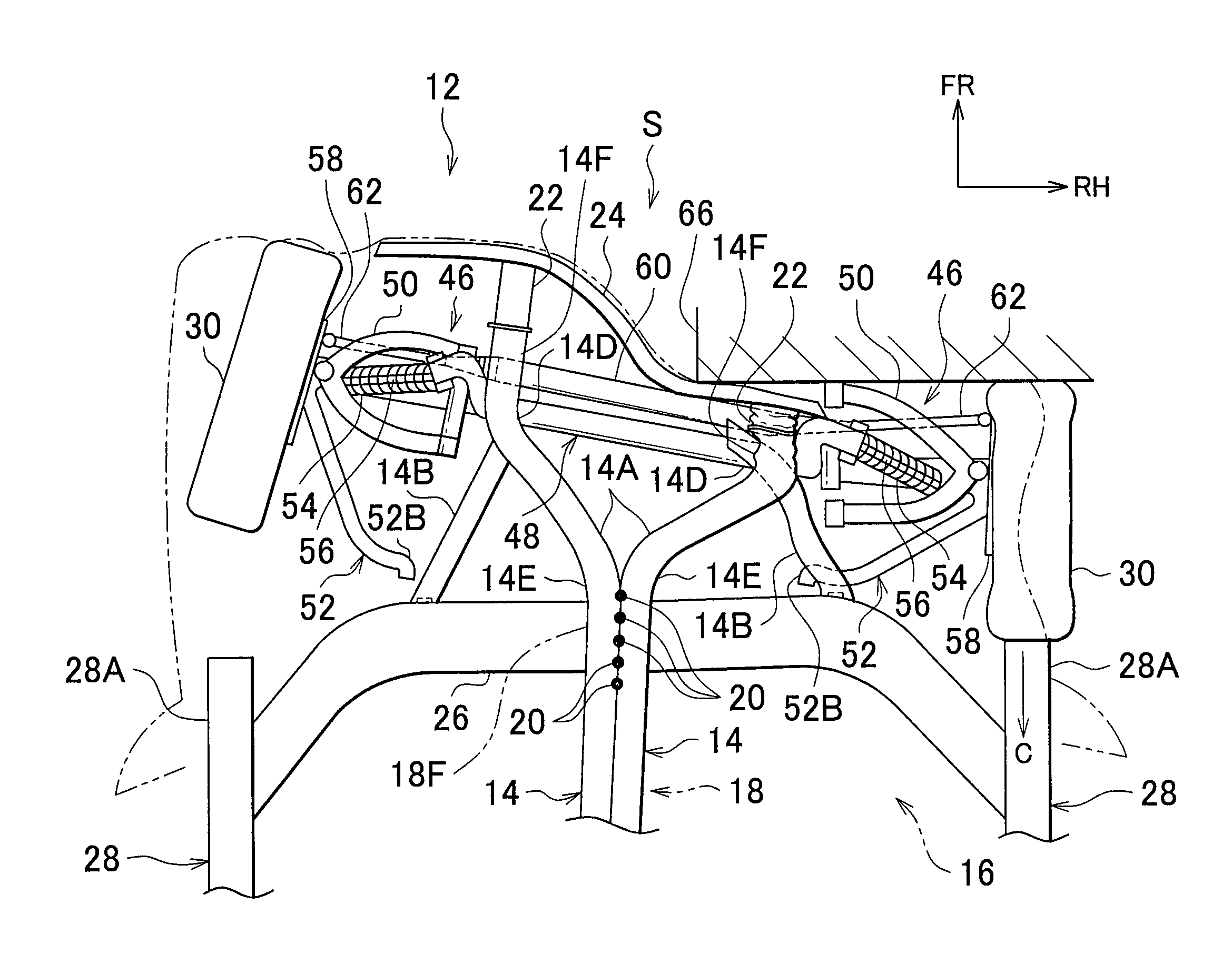
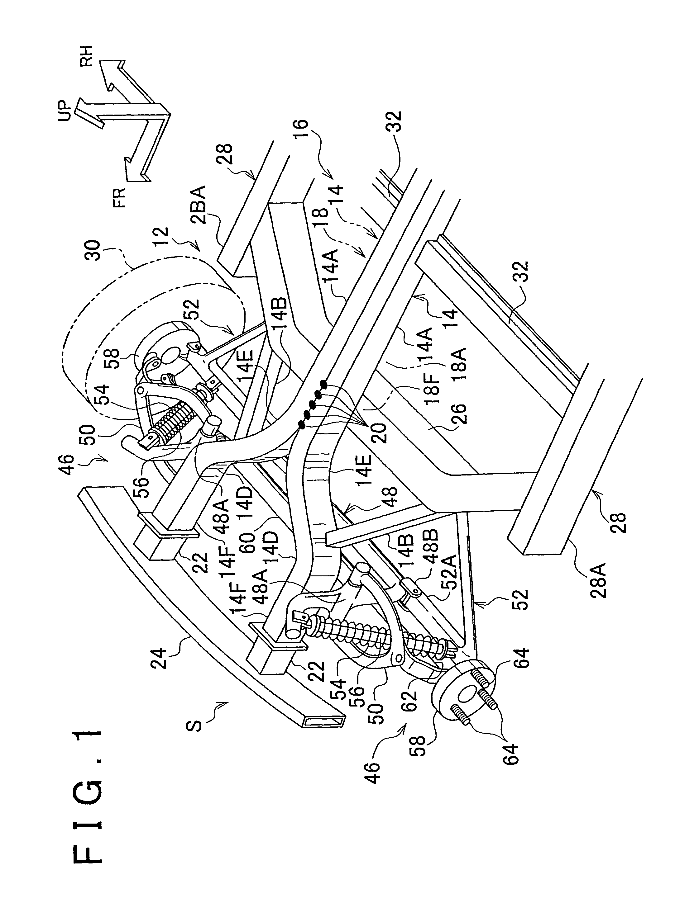
[0034]Example embodiments of the present invention will be described in greater detail below with reference to the accompanying drawings. In FIG. 1, a vehicle frame structure S according to an example embodiment relates to a frame structure of a vehicle 12 having a power unit (see FIG. 2) arranged in the rear, for example. This vehicle frame structure S has side members 14.

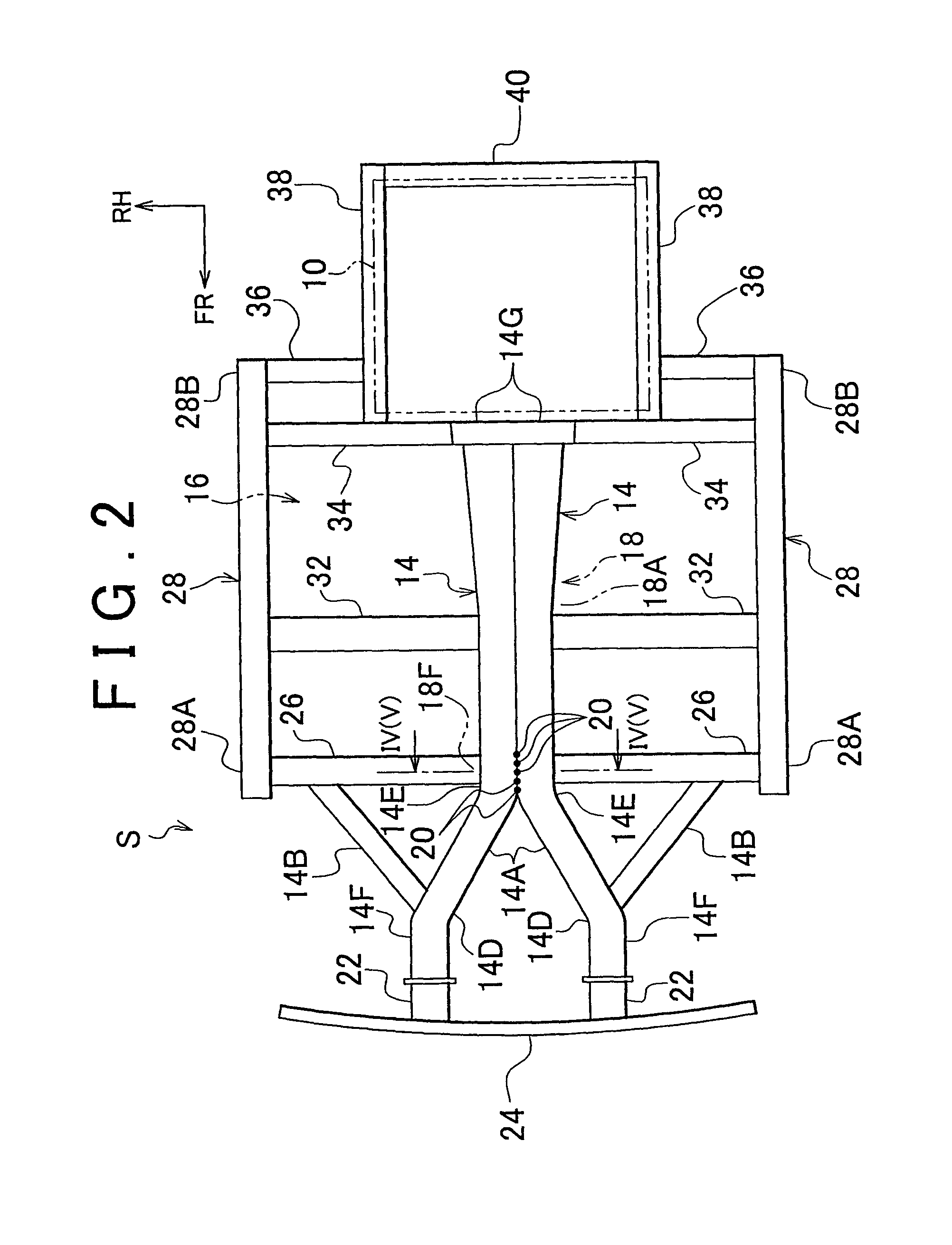
[0035]As shown in FIGS. 1 and 2, these side members 14 are frame members which extend in the longitudinal direction of the vehicle on both sides in the vehicle width direction. Each of these side members 14 branches off in a direction toward the rear of the vehicle from a front side member 14F at the front of the vehicle into an inner member 14A which is toward the inside in the vehicle width direction and an outer member 14B which is toward the outside in the vehicle width direction. The inner members 14A extend toward the rear of the vehicle along a tunnel portion 18 (see FIG. 4)) of a floor 16 and are connected...


PUM


Abstract

A vehicle frame structure includes a tunnel portion provided in a floor and left and right side members. Each of the side members includes a front side member, an inner member, and an outer member. The inner and outer members branch off from the front side member in a direction toward the rear of the vehicle. The inner member extends toward the rear of the vehicle along the tunnel portion. The inner members of the left and right side members are connected together by a plurality of connecting portions in the longitudinal direction of the vehicle at least at a location corresponding to a front portion side of the tunnel portion. These connecting portions break when a front impact load is input to at least one of the side members.

Description

CROSS-REFERENCE TO RELATED APPLICATIONS[0001]This application is a national phase application of International Application No. PCT / IB2009 / 006015, filed Jun.22, 2009, and claims the priority of Japanese Application No. 2008-164175, Jun. 24, 2008, the contents of both of which are incorporated herein by reference.BACKGROUND OF THE INVENTION[0002]1. Field of the Invention[0003]The invention relates to a vehicle frame structure.[0004]2. Description of the Related Art[0005]Japanese Patent Application Publication No. 2003-2248(JP-A-2003-2248) describes a structure in which a floor tunnel front and a floor tunnel rear, which are formed of extruded material that forms a floor tunnel which extends in the longitudinal direction of the vehicle, are connected together by a cast joint. When a front impact load is input to the floor tunnel from the front of the vehicle during a frontal collision of the vehicle, this joint (only this joint) deforms, thereby absorbing the energy from the collision....

Claims


Application Information

Patent Timeline
Patent Type & Authority Patents(United States)
IPC IPC(8): B62D21/15
CPCB62D21/06B62D21/152
Inventor AJISAKA, SATOSHI
Owner TOYOTA JIDOSHA KK
Why Eureka
Try Eureka