

Electromagnetic vibration device and manufacturing method thereof
a technology of electromagnetic vibration and manufacturing method, which is applied in the direction of mechanical vibration separation, propulsion system, winding, etc., can solve the problems of difficult to meet the requirements of bonding, difficult to ensure bonding, so as to achieve enhanced stability and uniformity
- Summary
- Abstract
- Description
- Claims
- Application Information
AI Technical Summary
Benefits of technology
Problems solved by technology
Method used
Image

Examples
Embodiment Construction
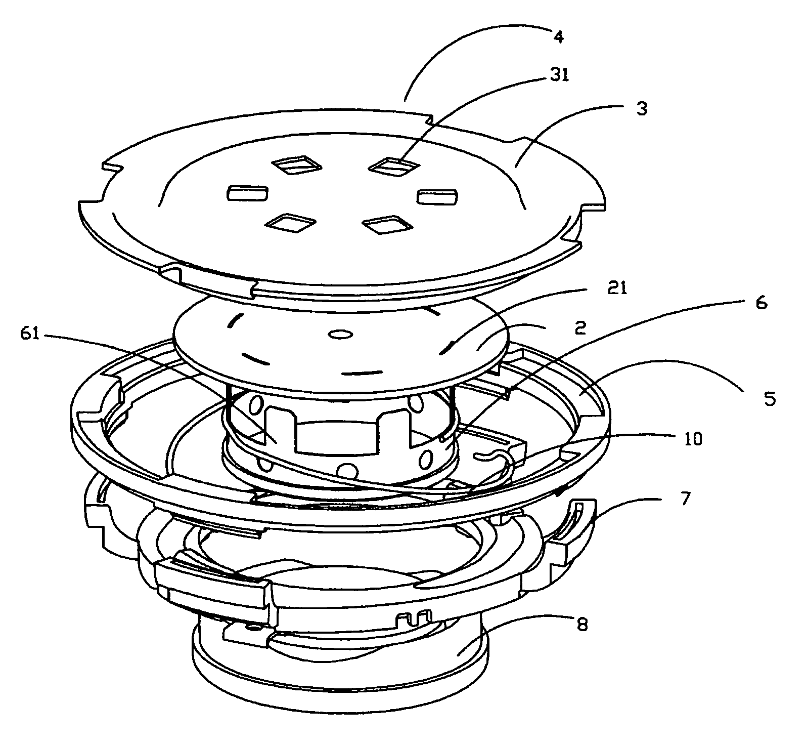
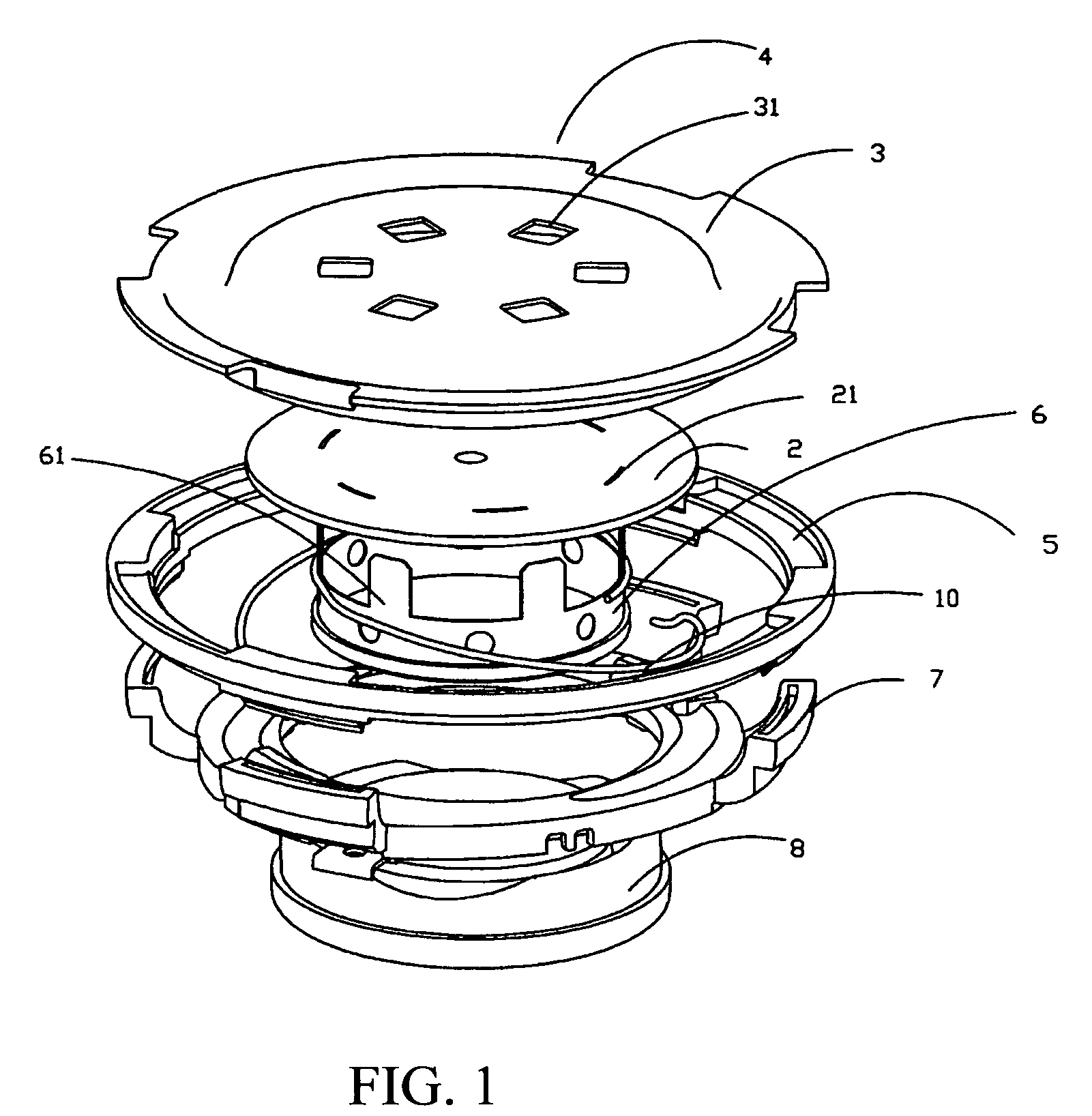
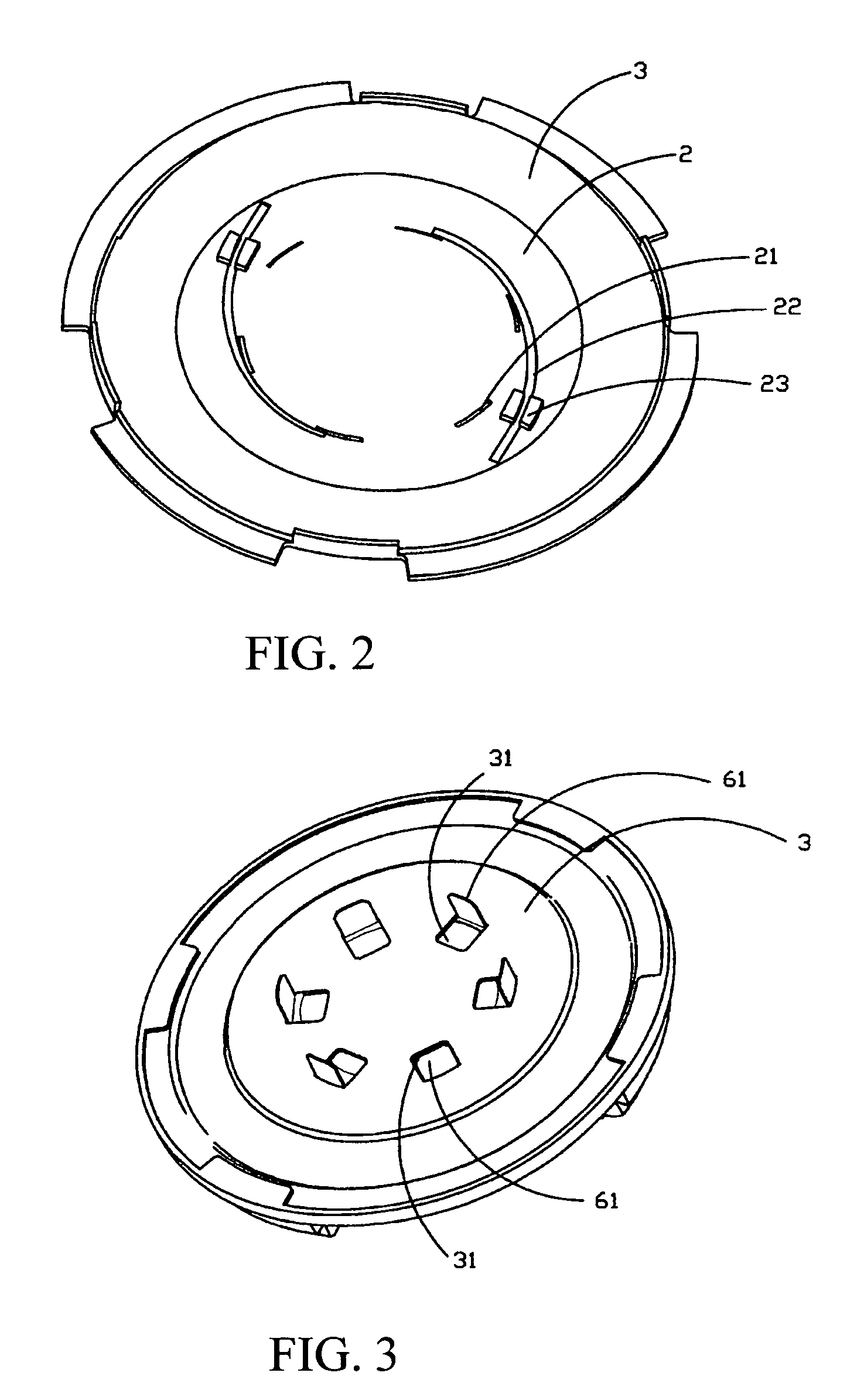
[0033]Referring to FIG. 1 of the drawings, an electromagnetic vibration device according to a first preferred embodiment of the present invention is illustrated, wherein the electromagnetic vibration device comprises a vibration member 2, a voice coil 6, a suspension element 3, an upper basin frame 5 a lower basin frame 7, a magnetic circuit system 8 supported by the lower basin frame 7. The vibration member 2 has a plurality of retaining slots 21, preferably six retaining slots 21, spacedly provided along the circumference thereof. Correspondingly, the voice coil 6 comprises a plurality of inserting members 61, preferably six inserting members 61, spacedly protruding therefrom to pass through the retaining slots 21 of the vibration member 2 respectively, as shown in FIG. 3. Each of the inserting members 61 has an upper bending portion arranged in such a manner that after the inserting member 61 is slidably inserted into the respective retaining slot 21, the upper bending portion of...
PUM
| Property | Measurement | Unit |
|---|---|---|
| conductive | aaaaa | aaaaa |
| stability | aaaaa | aaaaa |
| weight | aaaaa | aaaaa |
Abstract
Description
Claims
Application Information