Multibeam coherent laser diode source (embodiments)

a laser diode and coherent technology, applied in the field of optoelectronics, can solve the problems of not being able to realize high-power single-frequency diodes, further increase output power, etc., and achieve the effects of reducing production costs, improving efficiency, and reducing output power

Inactive Publication Date: 2013-03-19
GENERAL NANO OPTICS
View PDF7 Cites 13 Cited by
  • Summary
  • Abstract
  • Description
  • Claims
  • Application Information

AI Technical Summary

Benefits of technology

[0005]The technical result of the proposed diode source of multibeam, coherent amplified laser emission with various required emission outputs in a wide wavelength range is the increase of many times (one-three and more orders of magnitude) of output power of its amplified laser emission for stable single-frequency and single-mode laser types of oscillation, the increase of efficiency, reliability, life time and modulation speed with significant simplification of technology for source manufacturing and cut in the production costs.
[0006]The technical result of the proposed diode source of multibeam, coherent amplified laser emission with various required emission outputs in a wide wavelength range is the increase of many times (one-three and more orders of magnitude) of output power of its amplified laser emission for stable single-frequency and single-mode laser types of oscillation, the increase of efficiency, reliability, life time and modulation speed with significant simplification of technology for source manufacturing and cut in the production costs.
[0012]In the preferred embodiment in the lateral confinement region of the master laser there are at least one dividing-confinement subregion and at least one confinement subregion, at that the dividing-confinement subregion of a specified width is on both lateral sides of the active lasing region of the master laser from the heterostructure surface to a specified depth, not reaching the depth of location of the active layer, the confinement subregion is on both lateral sides of said dividing-confinement subregion from the heterostructure surface to a specified depth exceeding the depth of location of the active layer. The unusual lying of the confinement subregion (with crossing the active layer) provides the mode stability of laser emission at increased laser output powers.
[0033]In the preferred embodiment in the lateral confinement region of the master laser there are at least one dividing-confinement subregion and at least one confinement subregion, and the dividing-confinement subregion of a specified width is on both lateral sides of the active lasing region of the master laser from the heterostructure surface to a specified depth, not reaching the depth of location of the active layer, the confinement subregion is on both lateral sides of said dividing-confinement subregion from the heterostructure surface to a specified depth exceeding the depth of location of the active layer. The unusual lying of the confinement subregion (with crossing the active layer) provides the mode stability of laser emission at increased laser output powers.

Problems solved by technology

At the same time the prototype diode laser limits further increase of output power with simultaneous high quality of its laser emission, namely, it is not possible to realize high-power single-frequency diode sources of multibeam coherent emission (with a perfection factor M2 near one) as two-stage integrated combinations of a master diode laser and diode optical amplifiers with output of amplified laser emission both in the horizontal and in the vertical plane.

Method used


Image

  • Multibeam coherent laser diode source (embodiments)
  • Multibeam coherent laser diode source (embodiments)
  • Multibeam coherent laser diode source (embodiments)

Examples


Embodiment Construction

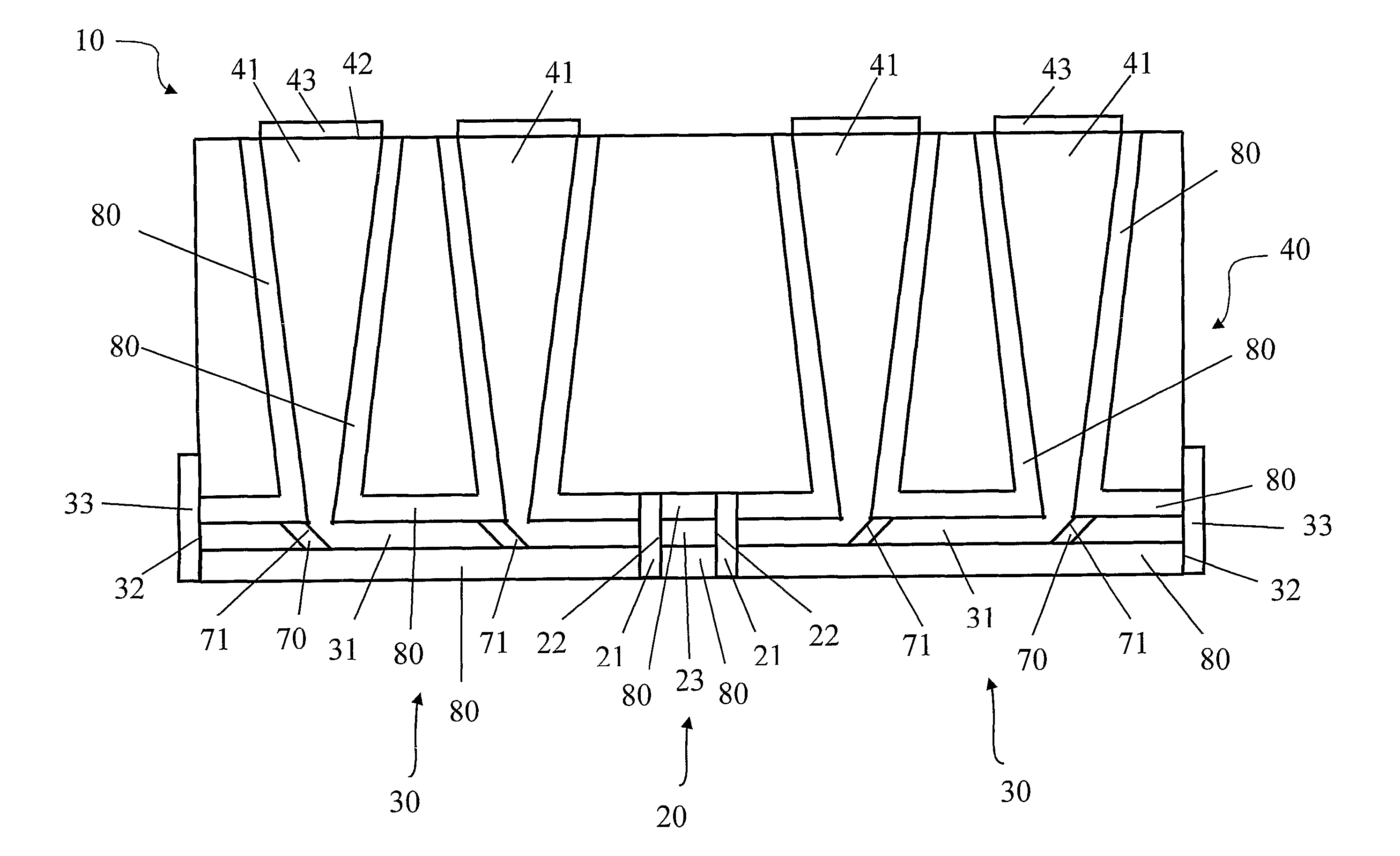
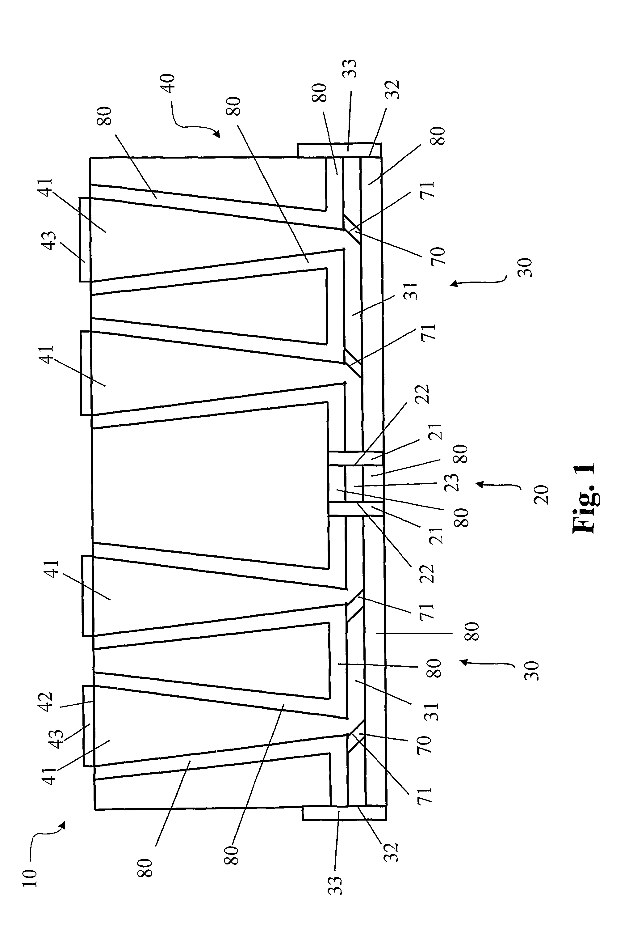
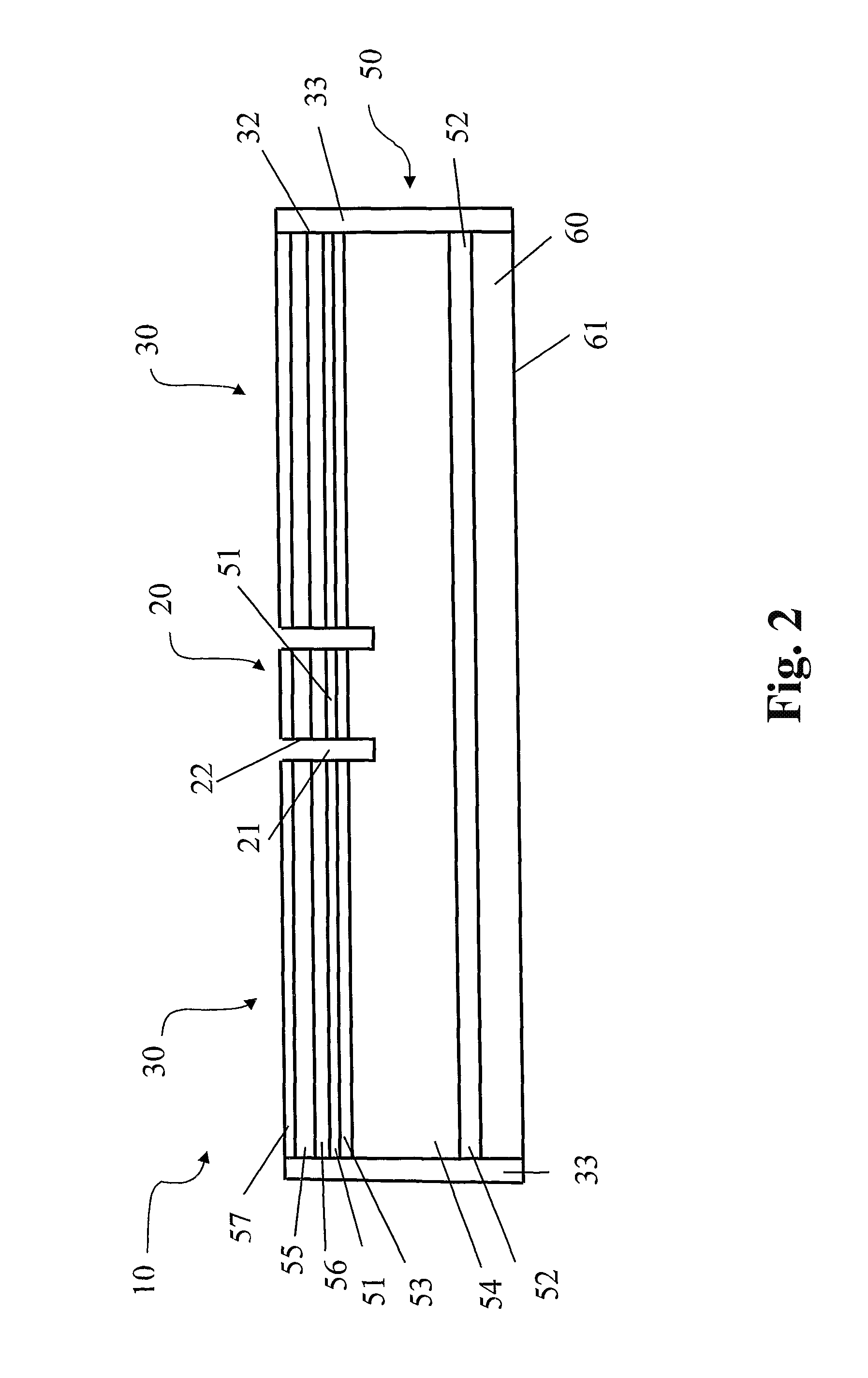
[0056]Hereinafter the invention is explained by the description of concrete embodiments with references to the enclosed drawings. The given examples of the embodiments of the diode source of multibeam coherent laser emission (DSMCLE) and a diode source of multibeam coherent laser emission with vertical emission output (DSMCLE-VE) are not the only ones and assume the availability of other realizations (including the known wavelength ranges), the features of which are reflected in the sum of the distinctions according to the claim.

[0057]In the DSMCLE designs proposed for consideration and represented in FIGS. 1-8 the following designations are given:[0058]10—Proposed DSMCLE.[0059]20—Master diode laser. Its components:[0060]21—Nontransmitting reflector of optical resonator hereinafter referred to as the nontransmitting optical reflector,[0061]22—Optical facet of optical resonator,[0062]23—Stripe active lasing region.[0063]30—Linear amplifier. Its components:[0064]31—Stripe active ampli...


PUM


Abstract

A multibeam coherent laser diode source comprises a master laser, a linear amplifier and two perpendicular amplifiers. The master laser and amplifiers are in the form of a single heterostructure containing an active layer, two limiting layers and a radiation influx area with an influx layer. The heterostructure is characterized by the ratio of the refractive index of the heterostructure to the refractive index of influx layer. This ratio is determined from a range extending from one plus delta to one minus gamma, where delta and gamma are defined by a number much less than one and gamma is greater than delta. The linear amplifier is positioned so that optical axis of radiation propagation from master laser coincides with the axis of the linear amplifier. Each perpendicular amplifier has output edge and is positioned so that its optical axis is situated at right angle to the axis of linear amplifier.

Description

FIELD OF THE INVENTION[0001]The invention relates to key components of optoelectronic engineering—to compact, high-power, high-efficiency sources of laser coherent emission in a wide wavelength range, namely, to a diode source of multibeam coherent emission with horizontal emission output and to a diode source of multibeam coherent emission with vertical emission output, said sources being made as a two-stage combination of a master diode laser with diode optical amplifiers.DESCRIPTION OF THE RELATED ART[0002]Diode lasers of increased output power and improved laser beam quality are known from the following inventions: [U.S. Pat. No. 4,063,189, Xerox Corp., (US), 1977, H01S 3 / 19, 331 / 94.5 H], [RU Patent 2197048, V. I. Shveikin, V. A. Gelovani, 18 Feb. 2002, H01S 5 / 32].[0003]From the standpoint of the technical essence and the technical result being obtained, an exemplary prototype injection (hereinafter diode) laser is proposed in [RU Patent 2278455, V. I. Shveikin, 17 Nov. 2004, H0...

Claims


Application Information

Patent Timeline
Patent Type & Authority Patents(United States)
IPC IPC(8): H01S3/13
CPCH01S5/026H01S5/1085H01S5/4006H01S5/42H01S5/0265H01S5/1007H01S5/1064H01S5/22H01S5/2214H01S5/32H01S5/06
Inventor SHVEYKIN, VASILIY IVANOVICHGELOVANI, VIKTOR ARCHILOVICHSONK, ALEKSEY NIKOLAEVICH
Owner GENERAL NANO OPTICS
Why Eureka
Try Eureka