High resolution wind measurements for offshore wind energy development

a high-resolution, wind-energy technology, applied in the direction of volume measurement, height/levelling measurement, special data processing applications, etc., can solve the problems of inability to place every kilometer over the entire ocean surface, significant land contamination effects near land-sea boundaries, and inaccurate or true wind-power measurement of buoy calculations

Inactive Publication Date: 2013-03-19
CALIFORNIA INST OF TECH
View PDF2 Cites 8 Cited by
  • Summary
  • Abstract
  • Description
  • Claims
  • Application Information

AI Technical Summary

Problems solved by technology

Energy is a critical issue facing all from local to regional, national, and international levels.
While model analyses are available in a number of selected regions, there are discrepancies among models and significant land contamination effects near land-sea boundaries [2].
Accordingly, buoy calculations are not accurate or truly representative of wind as the distance from the buoy increases.
While additional buoys may be utilized, they cannot be placed every kilometer over the entire ocean surface and still only provide limited point data.
Therefore, the extreme costs of manufacturing, deploying, maintaining, and replenishing such a global massive buoy system over a decade are prohibitive let alone any other associated issues.
Wind speed can be measured by satellite synthetic aperture radars; however, data are limited in accuracy, in time, and in space.
However, due to the original coarse resolution (e.g., 25 km) and land contamination effects, standard wind products from the scatterometer missions are not valid by 2 pixels or 50 km away from shore.
While it is desirable for a wind farm to locate at some distance (˜10 km) away from shore for higher and steadier wind speeds and because of issues related to ocean view, noise, navigation, security, and environmental impacts, wind tower technologies and bathymetry may limit the distance to within a few tens of km from shore (˜50-100 km).
Thus, the standard coarse low-resolution satellite wind products from satellite scatterometer data are neither useful nor applicable.
However, such approaches require that radar backscatter remains unchanged in each high-resolution pixel during the period of data acquisition used in the resolution enhancement process (similar to requiring a patient to stay still while the CT scan is made), and are not applicable to backscatter data acquired over ocean surface that are rapidly variable in time and in different azimuth angles.
These backscatter variations invalidate the fundamental requirement of backscatter invariant for the deconvolution approach to be applicable.

Method used


Image

  • High resolution wind measurements for offshore wind energy development
  • High resolution wind measurements for offshore wind energy development
  • High resolution wind measurements for offshore wind energy development

Examples


Embodiment Construction

[0024]In the following description, reference is made to the accompanying drawings which form a part hereof, and which is shown, by way of illustration, several embodiments of the present invention. It is understood that other embodiments may be utilized and structural changes may be made without departing from the scope of the present invention.

Overview

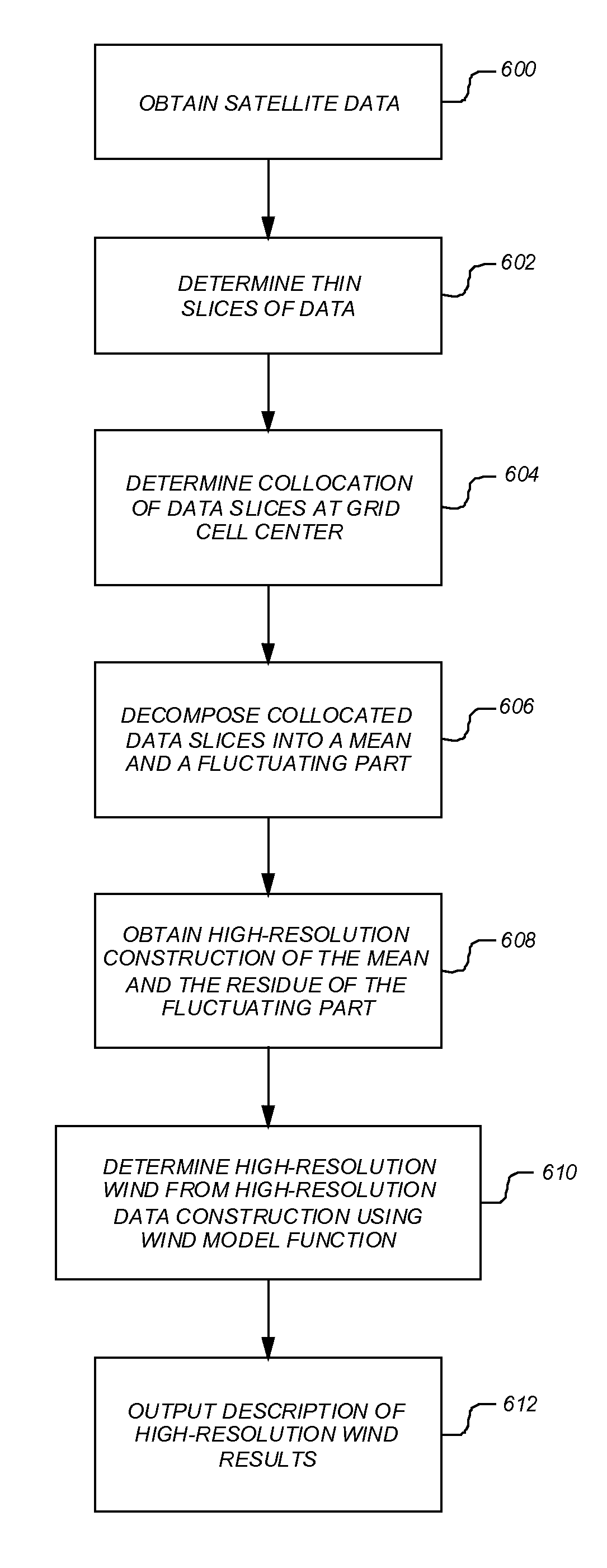
[0025]One or more embodiments of the invention overcome the problems of the prior art by utilizes a transform operation that is applied on the mean and fluctuating parts of targeted pixels to construct data in a high-resolution grid at 1-km postings for wind measurements over water surfaces such as oceans or lakes.

Hardware and Software Environment

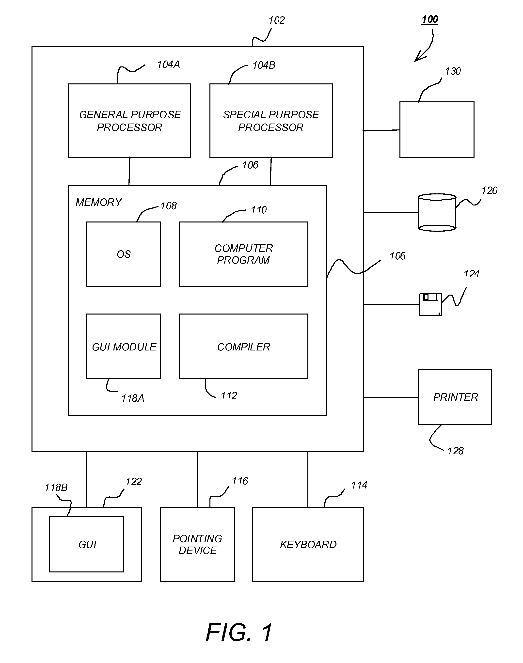
[0026]FIG. 1 is an exemplary hardware and software environment 100 used to implement one or more embodiments of the invention. The hardware and software environment includes a computer 102 and may include peripherals. Computer 102 may be a user / client computer, server computer, or may be a d...


PUM


Abstract

A method, apparatus, system, article of manufacture, and computer readable storage medium provide the ability to measure wind. Data at a first resolution (i.e., low resolution data) is collected by a satellite scatterometer. Thin slices of the data are determined. A collocation of the data slices are determined at each grid cell center to obtain ensembles of collocated data slices. Each ensemble of collocated data slices is decomposed into a mean part and a fluctuating part. The data is reconstructed at a second resolution from the mean part and a residue of the fluctuating part. A wind measurement is determined from the data at the second resolution using a wind model function. A description of the wind measurement is output.

Description

CROSS-REFERENCE TO RELATED APPLICATIONS[0001]This application claims the benefit under 35 U.S.C. Section 119(e) of the following co-pending and commonly-assigned U.S. provisional patent application(s), which is / are incorporated by reference herein:[0002]Provisional Application Ser. No. 61 / 173,916, filed on Apr. 29, 2009, by Son Van Nghiem, and Gregory Neumann, entitled “HIGH-RESOLUTION WIND MEASUREMENTS FOR OFFSHORE WIND ENERGY DEVELOPMENT,”.STATEMENT REGARDING FEDERALLY SPONSORED RESEARCH AND DEVELOPMENT[0003]The invention described herein was made in the performance of work under NASA contract number NAS7-1407, and is subject to the provisions of Public Law 96-517 (35 USC 202) in which the Contractor has elected to retain title.BACKGROUND OF THE INVENTION[0004]1. Field of the Invention[0005]The present invention relates generally to offshore wind energy development, and in particular, to a method, apparatus, and article of manufacture for determining a fundamental dataset of offsh...

Claims


Application Information

Patent Timeline
Patent Type & Authority Patents(United States)
IPC IPC(8): G01W1/00G06F7/60G01C5/00G01S13/00
CPCG01S13/9029G01S13/955G01W1/02F05B2240/95Y02A90/10
Inventor NGHIEM, SON VANNEUMANN, GREGORY
Owner CALIFORNIA INST OF TECH
Why Eureka
Try Eureka