Low hysteresis sensor

a sensor and low hysteresis technology, applied in the direction of using electrical/magnetic means, magnetic materials, electrical/magnetic measuring arrangements, etc., can solve the problems of increasing the linearity of the sensor, the disadvantage of complex structure and operation of the sensor, and the reduction of material hysteresis, so as to achieve the effect of increasing the accuracy of the sensor and reducing the hysteresis of the material

Active Publication Date: 2013-03-26
VACUUMSCHMELZE GMBH & CO KG
View PDF41 Cites 3 Cited by
  • Summary
  • Abstract
  • Description
  • Claims
  • Application Information

AI Technical Summary

Benefits of technology

[0008]The methods and apparatus disclosed herein are is therefore based on the problem of specifying a sensor which has a simple structure and permits an accurate measurement of a magnetic field generating event, such as an electric current or the movement of a permanent magnet.
[0011]As a coercitive field strength is reduced, the material hysteresis of the flux conducting soft magnetic element and thus the sensor hysteresis are increasingly reduced. This results in an increase in sensor linearity. A low sensor hysteresis and an increased sensor linearity result in a more accurate measurement of the magnetic flux which is generated as the permanent magnet is displaced or rotated relative to the flux conducting soft magnetic element, or as the current flows. The accuracy of the sensor is improved by using this alloy for the flux conducting soft magnetic element.
[0012]Using a soft magnetic 80% NiFe permalloy involves the disadvantage of a very low saturation below 0.8 T and high material costs due to the high Ni content. The sensor described herein at least in part offers a material saturation of more than 0.85 T. In order to minimise the drop in material saturation at elevated operating temperatures, the Curie temperature Tc should not be too low.
[0014]The alloy of the flux conducting soft magnetic element therefore offers a combination of properties which are particularly suitable for sensors such as position and current sensors, because their material hysteresis is reduced and the accuracy of the sensor is increased.

Problems solved by technology

However, sensors of this type have the disadvantage that measuring accuracy is limited by the material hysteresis of the flux conducting soft magnetic element.
However, this sensor has the disadvantage of a complicated structure and operation.
This results in an increase in sensor linearity.
Using a soft magnetic 80% NiFe permalloy involves the disadvantage of a very low saturation below 0.8 T and high material costs due to the high Ni content.

Method used


Image

  • Low hysteresis sensor
  • Low hysteresis sensor
  • Low hysteresis sensor

Examples


first embodiment

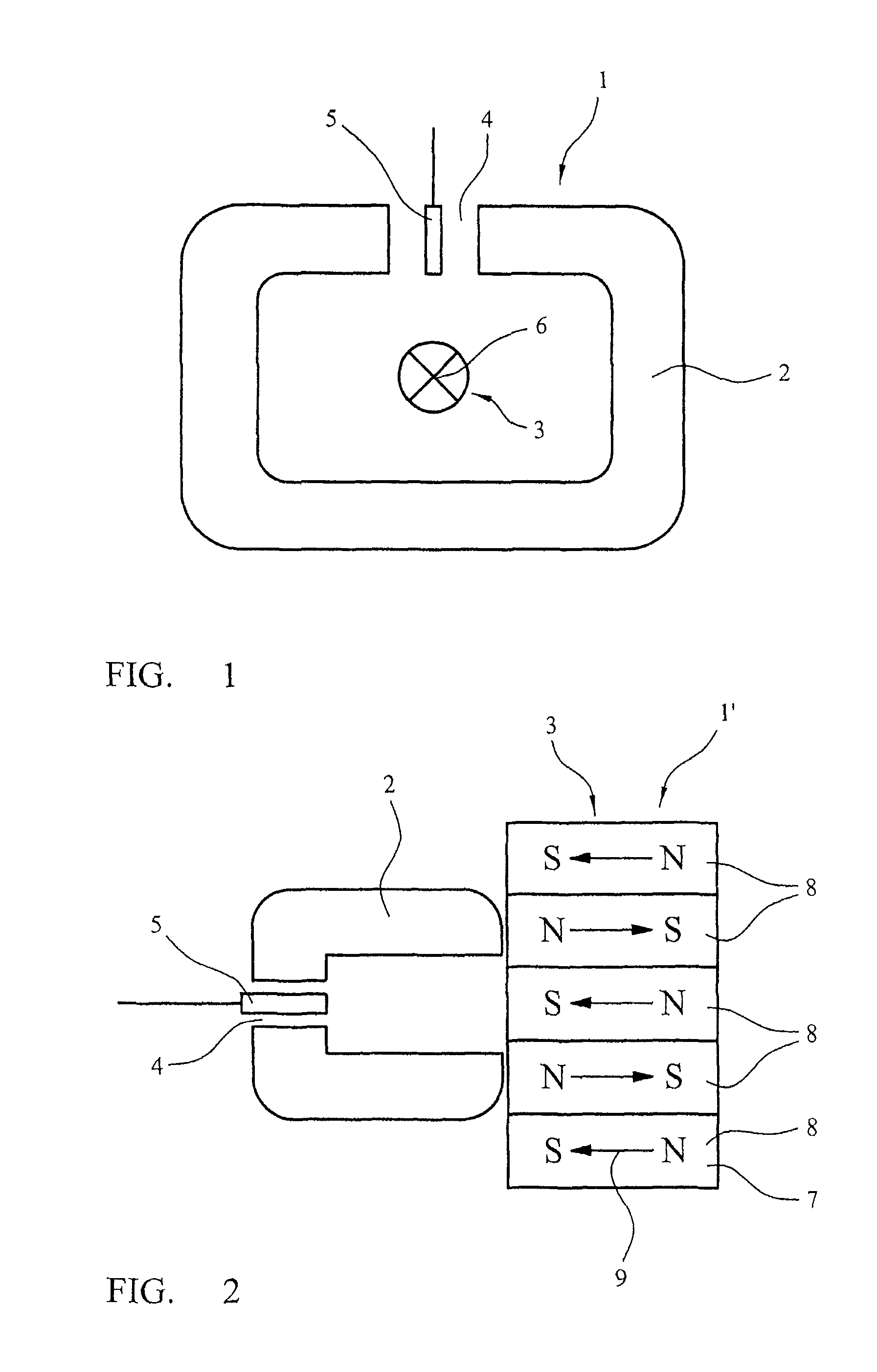
[0030]In a first embodiment, the magnetic field source comprises a direct current or an alternating current which generates a magnetic field as it flows through a conductor. The magnitude of the generated magnetic field is proportional to the magnitude of the flowing current. In a particular embodiment, the sensor may further comprise at least one winding wound around the flux conducting soft magnetic element. The current to be measured flows through this winding.

second embodiment

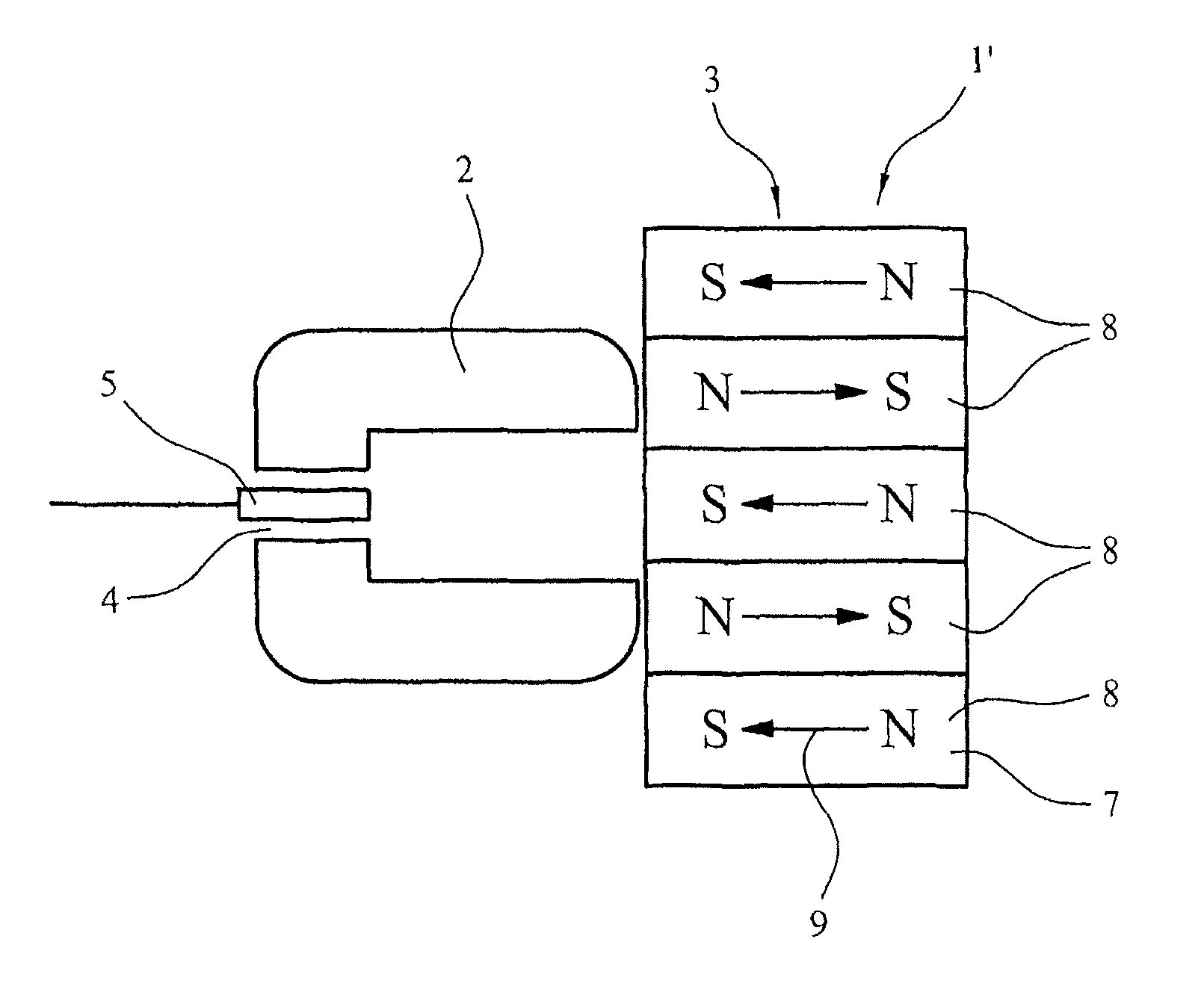
[0031]In a second embodiment, the magnetic field source comprises a permanent magnet which is movable relative to the flux conducting soft magnetic element. The magnitude of the change of the generated magnetic flux is proportional to the magnitude of the change in the position of the permanent magnet. As a result, the position of the permanent magnet can be determined from the change of the magnetic flux. In a particular embodiment, the permanent magnet can be connected to an object the position of which is to be measured. This may involve a linear or rotary relative movement which is detected by the sensor.

[0032]In a particular, the permanent magnet may have a plurality of areas with alternating directions of magnetisation. These areas may be provided with a plurality of magnets mounted on a yoke. Alternatively, the permanent magnet may be a single unit with varying magnetisation.

[0033]The flux conducting soft magnetic element may be shaped in various ways. In one embodiment, a si...


PUM

PropertyMeasurementUnit
temperatureaaaaaaaaaa
Curie temperatureaaaaaaaaaa

Abstract

A sensor comprises a magnetic field source, at least one flux conducting soft magnetic element with at least one air gap and at least one magnetic field sensor located in the air gap and measuring a change of the magnetic field of the magnetic field source. The flux conducting soft magnetic element consists of 35% by weight≦Ni≦50% by weight, 0% by weight≦Co≦2% by weight, 0% by weight≦Mn≦1.0% by weight, 0% by weight≦Si≦0.5% by weight and 0.5% by weight≦Cr≦8% by weight and / or 0.5% by weight≦Mo≦8% by weight, wherein (Mo+Cr)≦8, rest iron and unavoidable impurities.

Description

FIELD[0001]Disclosed herein is a low hysteresis sensor, such as a current sensor or a position sensor, wherein the current or the position is measured by means of the change in a generated magnetic field in an open magnetic circuit.DESCRIPTION OF RELATED ART[0002]Sensors can measure changes of a magnetic field which are caused by an event to be measured. Using one or more flux conducting soft magnetic elements, the generated magnetic field is concentrated at a flux detector located in an air gap in the flux conducting soft magnetic element. Owing to the air gap, the magnetic circuit is open.[0003]The magnetic field may for example be generated by a current or by a movement of a permanent magnet. Depending on the source of the generated magnetic field, the sensor may be a current sensor or a position sensor. DE 100 11 047 A1 discloses a current sensor, while DE 198 25 433 A1 discloses a position sensor; both are based on this measuring principle.[0004]However, sensors of this type ha...

Claims


Application Information

Patent Timeline
Patent Type & Authority Patents(United States)
IPC IPC(8): G01R33/02G01B7/14
CPCC22C19/057H01F1/15308C22C30/00C22C38/02C22C38/04C22C38/40C22C38/44G01B1/00G01B7/003G01D5/142G01R15/207G01R33/0029G01R33/0035G01R33/063H01F1/14708C22C19/058H01F1/14716G01B7/10G01R15/202G01R19/15G01R33/07
Inventor TENBRINK, JOHANNESPIEPER, WITOLDKRAUS, BURKARDGERSTER, JOACHIM
Owner VACUUMSCHMELZE GMBH & CO KG
Why Eureka
Try Eureka