
Manufacturing method for eyelet and structure thereof

a manufacturing method and eyelet technology, applied in the field of eyelet for tarpaulin, can solve the problems of increased process load, easy loosening of eyelet, and inability to use the whole of the tarpaulin fabric, and achieve the effect of simple production and mounting process and low production cos

Inactive Publication Date: 2013-04-02
QINGDAO GYOHA & TECH PLASTICS
View PDF8 Cites 16 Cited by
  • Summary
  • Abstract
  • Description
  • Claims
  • Application Information

AI Technical Summary

Benefits of technology

The present invention aims to solve the problems associated with conventional eyelets in tarpaulin fabric by providing an eyelet that can be fixed rigidly, recycled with the fabric, and have low production and mounting costs. The technical effects of the invention are to offer a more efficient and cost-effective solution for eyelet installation in tarpaulin fabric.

Problems solved by technology

First, the rivet-coupled way between the lower cylindrical body and the upper disc of the eyelet results in the failure of the close connection between the eyelet and the tarpaulin fabric. That is, a clearance between the eyelet and the tarpaulin fabric is left, and if an external force is applied to the rope passed through the eyelet, the eyelet becomes easily loose such that it is moved together with the rope over the tarpaulin fabric. In some cases, the eyelet may be deformed and even deviated from the tarpaulin fabric. Furthermore, the tarpaulin fabric can be torn around the fixed portion to the eyelet, and if it is so, the torn portion can be rapidly extended, which may cause the whole of tarpaulin fabric to be useless.
Second, most of tarpaulin fabrics are made of plastic that is different from the aluminum eyelet material. According to the environment protection requirements prescribed in many countries, when the usage duration of the tarpaulin fabric elapses, the aluminum eyelet should be inconveniently detached from the tarpaulin fabric because it is not recycled, which makes the load of the process increased. On the other hand, the hard plastic eyelet can be recycled, but it should be separately detached from the tarpaulin fabric because of the hardness difference of the materials between the hard plastic eyelet and the tarpaulin fabric.
Third, since the aluminum eyelet and the hard plastic eyelet are all hard, they are easily deformed to undesirably form an edge portion around the outer peripheral surface thereof after the usage of a predetermined period of time, which causes an operator to be hurt on his or her hand when the rope is passed therethrough.
Fourth, the production costs are relatively high.
Fifth, the manufacturing process is relatively complicated.
Sixth, since the eyelet has the different structures between the lower cylindrical body and the upper disc, the parts are delivered individually during the production of the eyelet, and the process of mounting the eyelet is complicated, while having the low efficiency.
Finally, the eyelet has a relatively complicate shape, and since the upper cylindrical body has a predetermined height, relatively large space for the delivery is occupied.

Method used


Image

  • Manufacturing method for eyelet and structure thereof
  • Manufacturing method for eyelet and structure thereof
  • Manufacturing method for eyelet and structure thereof

Examples


Embodiment Construction

[0039]Now, an explanation on a preferred embodiment of the present invention will be in detail given with reference to FIGS. 1 to 5.

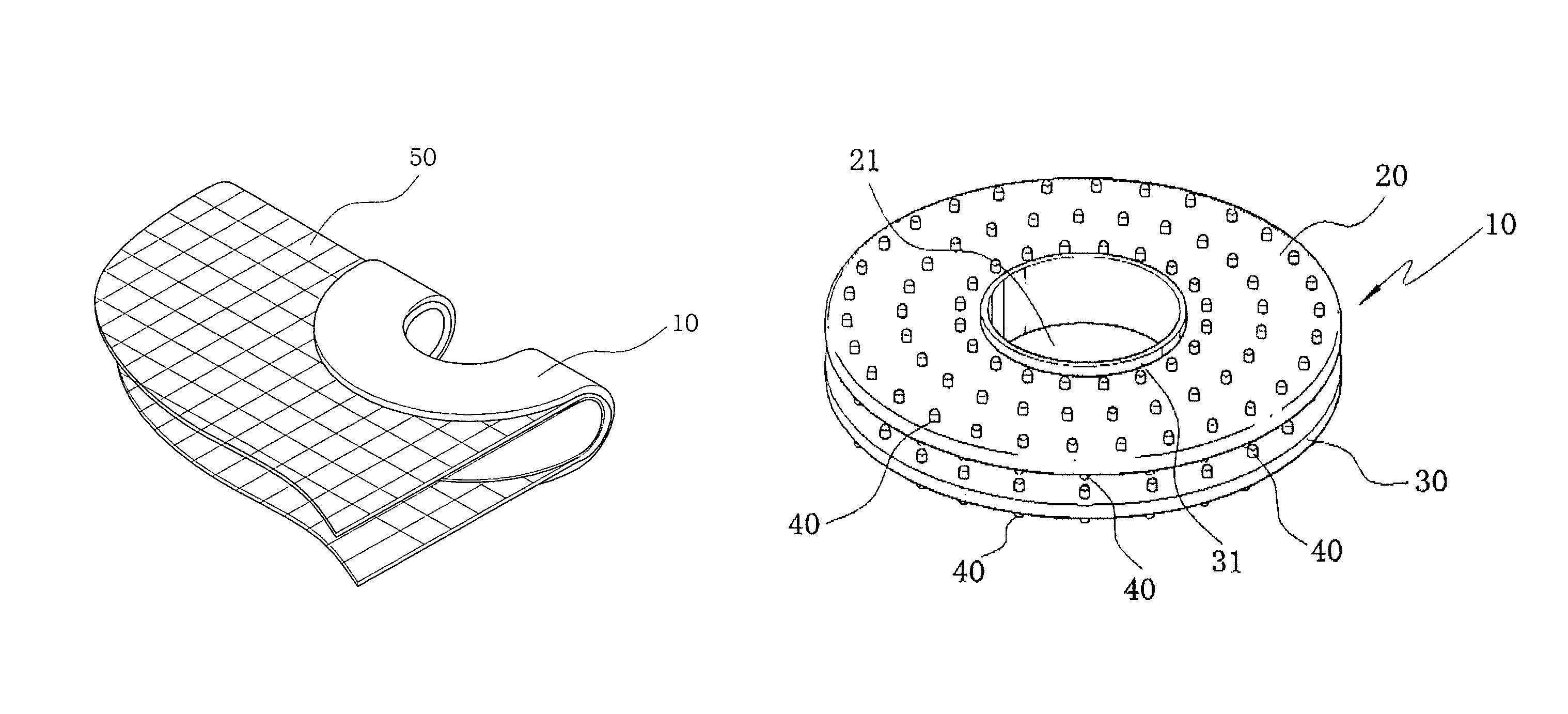
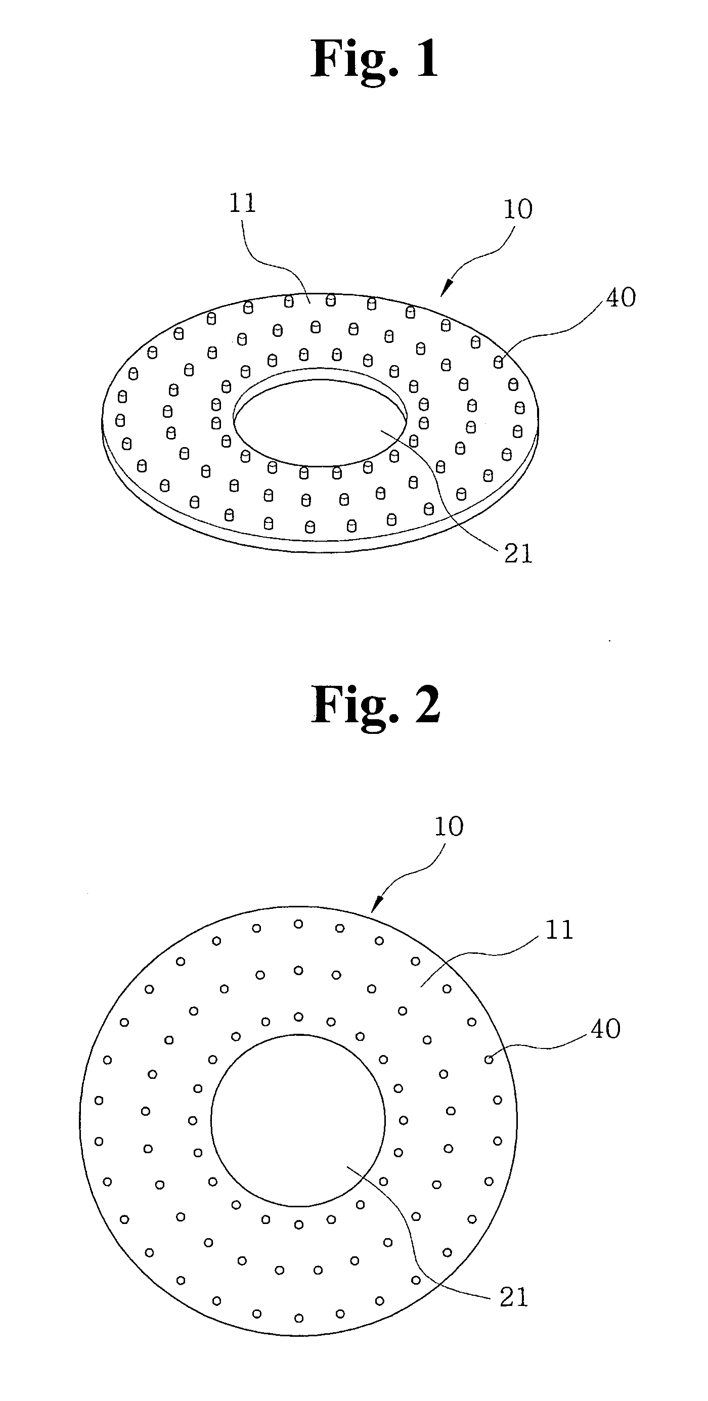
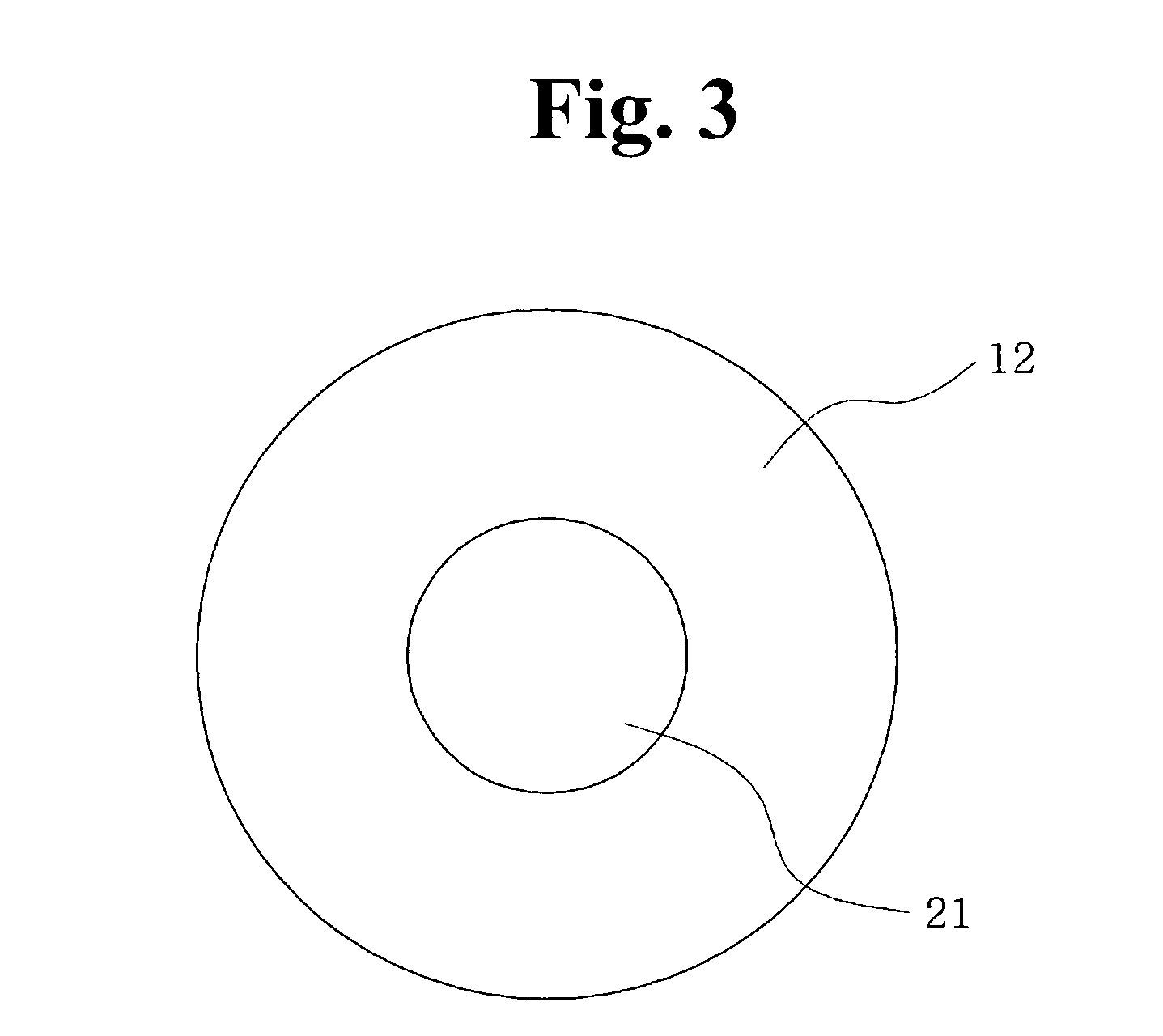
[0040]Upper and lower eyelet bodies 10 that are adapted to be fixed on the top and bottom surfaces of a tarpaulin fabric 50 have the same structure as each other and are in a shape of a generally round loop. Each of the upper and lower eyelet bodies 10 is generally flat at top and bottom surfaces 11 and 12 thereof. Each of the upper and lower eyelet bodies 10 is provided with a plurality of fixing protrusions 40 that are formed on the top surface 11 thereof in such a manner as to be arranged in a shape of at least three or more concentric circles. Each of the plurality of fixing protrusions 40 is protruded upwardly. The plurality of fixing protrusions 40 are arranged to form an inner concentric circle, an intermediate concentric circle and an outer concentric circle on the top surface 11 of each of the upper and lower eyelet bodies 10 in such a manner t...


PUM

PropertyMeasurementUnit
heightaaaaaaaaaa
diameteraaaaaaaaaa
diameteraaaaaaaaaa

Abstract

The present invention discloses a method for manufacturing an eyelet for a tarpaulin, the eyelet having upper and lower eyelet bodies each provided with a plurality of fixing protrusions formed in a shape of concentric circles on one surface thereof in such a manner that the plurality of fixing protrusions formed on the upper eyelet body confront to the plurality of fixing protrusions formed on the lower eyelet body, the method comprising the following steps of: a step of positioning the upper and lower eyelet bodies by using a conveying means in such a manner as to place the tarpaulin there between; a step of punching a given position on the tarpaulin fabric by means of a punching machine with an integrally-formed ultrasonic horn; a step of conveying the upper and lower eyelet bodies to a position of the ultrasonic horn and fusing the upper and lower eyelet bodies to the tarpaulin through the compression of the ultrasonic horn; a step of fusing a protruded part extending upwardly from the circumference of a through-hole of the lower eyelet body by compression in the ultrasonic-fusing step to form an inner circumferential edge part; and a step of passing a rope through the through-hole of the eyelet mounted on the tarpaulin.

Description

[0001]This application claims priority to Chinese Application No. 20040099243.7 filed on Dec. 24, 2004 and is incorporated by reference, as if fully set forth herein.TECHNICAL FIELD[0002]The present invention relates to an eyelet for a tarpaulin, and more particularly, to a method for manufacturing an eyelet for a tarpaulin that is fixedly attached on the edge portion of a tarpaulin fabric for passing a rope there through and to an improved structure of such an eyelet.BACKGROUND ART[0003]A tarpaulin is widely used to cover articles in freight vehicles or warehouses so that the articles are kept safely in even rain or sunshine. Generally, a tarpaulin is used in such a fashion as to be secured at the edge portion thereof by means of a string or rope, and at this time, so as to prevent a tarpaulin fabric from being damaged, eyelets are attached along the edge portion of the tarpaulin fabric and the string or rope is passed through the eyelets. Then, the eyelet and the string or rope ar...

Claims


Application Information

Patent Timeline
Patent Type & Authority Patents(United States)
IPC IPC(8): A43C5/00A44B99/00
CPCA44B13/007A44B13/0094Y10T24/3742A44B17/00
Inventor CHUNG, DO-JIN
Owner QINGDAO GYOHA & TECH PLASTICS
Learn More