Catheter and method of making the same

a catheter and catheter technology, applied in the field of medical devices, can solve the problems of irritating sensitive tissue, a greater risk of occlusion of the aspiration channel, and less certain aspiration flow, so as to improve the flow rate and occlusion resistance, improve the flexibility of the aspiration channel, and improve the occlusion resistance.

Inactive Publication Date: 2013-04-02
MOSS GERALD
View PDF2 Cites 14 Cited by
  • Summary
  • Abstract
  • Description
  • Claims
  • Application Information

AI Technical Summary

Benefits of technology

[0019]Simple liquid flow through a gastrointestinal catheter is generally proportional to the 4th power of the I.D. The likelihood of occlusion is not so easily defined, but may reach a similar (or greater) value under encountered circumstances. Even modest increase in the I.D. profoundly improves flow rate and occlusion resistance.
[0020]In another embodiment, a fine cloth mesh sleeve, such as, but not limited to polyester, nylon, or a mixture thereof, tightly encases the otherwise exposed distal helical spring band is utilized. The fine cloth mesh sleeve is generally about 0.002″ thick, This allows free inflow of the gastric and intestinal liquids surrounding that section of the catheter, and provide longitudinal stability. The impervious plastic layer will overlay the proximal portion of the spring band, with an approximately one inch of overlap to secure the cloth mesh sleeve in place. The terminal end of the sleeve can be secured to the terminal end of the spring band with adhesive or by other mechanical means.
[0021]In still another embodiment, this cloth mesh sleeve will encase the entire length of underlying helical spring band. An extremely thin layer, about 0.00025″ of heat shrinkable polyester or polyolefin tubing can be applied to overlay the proximal segment of the catheter, making it impervious to fluid. Heat shrink tubing usually imparts a relative inflexibility to the underlying material. By making this heat shrink tubing ultra-thin, adequate flexibility is achieved. However, this layer may be at risk for “cutting” by the underlying stainless steel spring band. The cloth mesh sleeve between the heat shrink tubing and spring band would protect the former while minimizing the thickness.

Problems solved by technology

As the catheter encounters sharp bends and makes prolonged contact, it may irritate sensitive tissue.
However, the adequacy of aspiration flow is less certain.
Excess digestive juices and swallowed air that escape removal may be propelled downstream, to accumulate and cause distention.
Further, the aspiration channel is at greater risk for occlusion by the particulates and mucus encountered in the gastrointestinal fluids.
However, G-I motility of hospitalized patients is characteristically impaired by disease and / or trauma, including the trauma incident to surgery.
Abdominal distention exerts its harmful effects in several ways.
It reduces the ability of the patient to adequately breathe deeply, cough and clear secretions, predisposing to pneumonia.
It causes extreme discomfort and limits mobility.
It interferes with nutrient absorption.
The resulting undernourishment slows the healing process, reduces the patient's optimum resistance to infection, and increases the recovery time.
The bent catheter may kink, causing partial or total occlusion.
A 28 Fr catheter is too large and uncomfortable to insert transnasally in a patient.
The nasal catheters in current use are necessarily more slender, and therefore have lumens with compromised functionality.

Method used


Image

  • Catheter and method of making the same
  • Catheter and method of making the same
  • Catheter and method of making the same

Examples


Embodiment Construction

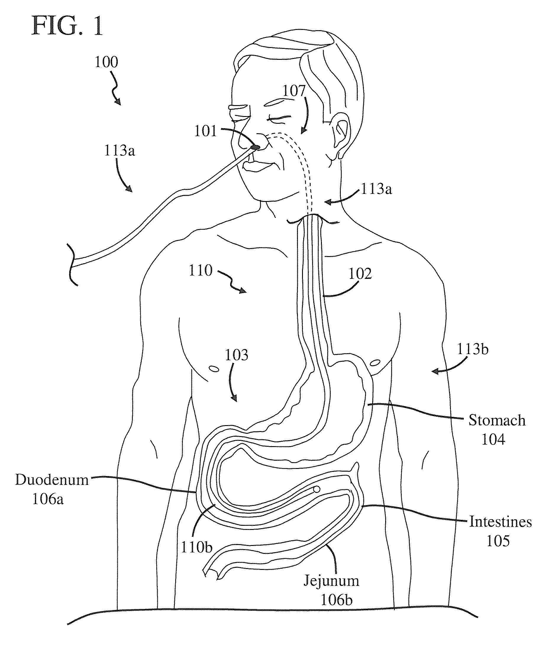
[0069]FIG. 1 is a front view of a person 100 with a catheter 110 inserted therein. It should be noted that catheter 110 can be used as many different medical devices, such as a feeding tube, aspirating tube, etc. Further, catheter 110 includes a single lumen in this embodiment, but it can include more than one lumen, if desired. An embodiment of catheter 110 which includes two lumens is often referred to as a dual lumen catheter. One example of a dual lumen catheter includes feeding and aspirating tubes, wherein the feeding tube extends through the aspiration tube. The feeding tube is positioned distal to but in close proximity (<5 cm) to the end of the aspiration tube, but still within the same anatomical segment of the G-I tract, e.g the duodenum. More information regarding dual lumen devices can be found in the references cited in the Background.

[0070]In this embodiment, catheter 110 has been positioned so it extends through a nasal passage 101 of person 100 and esophagus 102 and...


PUM


Abstract

A method of manufacturing a catheter includes positioning a resilient tube in a vacuum tube. An outer periphery of the resilient tube is sealed to the vacuum tube so a vacuum region can be formed therebetween. A dimension of a channel of the resilient tube is adjustable in response to adjusting the pressure of the atmosphere of the vacuum region. The dimension of the channel is adjusted so that a reinforcement member can be positioned therein.

Description

CROSS-REFERENCE TO RELATED APPLICATIONS[0001]This application is a Non-Provisional of U.S. Provisional Application No. 61 / 218,355, filed on Jun. 18, 2009, the contents of which are incorporated herein by reference in their entirety.BACKGROUND OF THE INVENTION[0002]1. Field of the Invention[0003]This invention relates generally to medical devices, such as catheters, and particularly to enteral feeding catheters.[0004]2. Description of the Related Art[0005]Feeding-decompression catheters must reside within the gastrointestinal (G-I) tract of patients for prolonged periods. A catheter may be delivered by direct penetration through the abdominal and gastrointestinal walls. Some directly placed catheters may then be directed to traverse the normal G-I channels to reach a more distal duodenal or jejunal feeding and / or aspiration site.[0006]Alternatively, the catheter may be introduced indirectly and less traumatically into the body through a natural opening (e.g., nasal passage), to then ...

Claims


Application Information

Patent Timeline
Patent Type & Authority Patents(United States)
IPC IPC(8): A61M25/00
CPCA61M25/0012A61M25/005A61M25/0052A61J15/0003A61M2025/0059A61J15/0069
Inventor MOSS, GERALD
Owner MOSS GERALD
Why Eureka
Try Eureka