Sheet processing apparatus and image forming system

a technology of image forming system and processing apparatus, which is applied in the direction of electrographic process, manufacturing tools, instruments, etc., can solve the problems of sheet buckled, follow-up problems, etc., and achieve the effect of reducing the strength of the end part of the sh

Inactive Publication Date: 2013-04-09
CANON KK
View PDF9 Cites 9 Cited by
  • Summary
  • Abstract
  • Description
  • Claims
  • Application Information

AI Technical Summary

Benefits of technology

[0010]According to the present invention, there is provided a sheet processing apparatus including: a punch portion which punches a hole at an end part of a sheet; a sheet discharge portion which discharges the sheet by pushing the end part of the sheet where the punch process is performed by the punch portion; and a controller which controls the sheet discharge portion, wherein the controller controls so that the sheet discharge portion discharges a sheet at a sheet discharging speed lower than a predetermined speed in accordance with punch process information that strength of a sheet end part is decreased by the punch process and is lower than predetermined sheet strength capable of being discharged at the predetermined speed.
[0011]According to the present invention, buckling at an end part of a sheet of which strength is decreased due to a punch process can be prevented. Accordingly, a sheet product on which a high quality punch process is performed can be provided to a user.

Problems solved by technology

Accordingly, when the sheets are stacked on the processing tray and discharged to the stack tray from the processing tray as an ordinary punch process with a few holes such as 2 to 4 holes, there is a fear that following problems occur.
At that time, when the sheet is thin, there is a fear that the sheet is buckled as the discharge member pushes out the end part of the punch-processed sheet.

Method used


Image

  • Sheet processing apparatus and image forming system
  • Sheet processing apparatus and image forming system
  • Sheet processing apparatus and image forming system

Examples


first embodiment

[0026]In the following, an image forming system constituted with an image forming apparatus main body and a sheet processing apparatus according to a first embodiment will be described.

General Configuration of Image Forming System

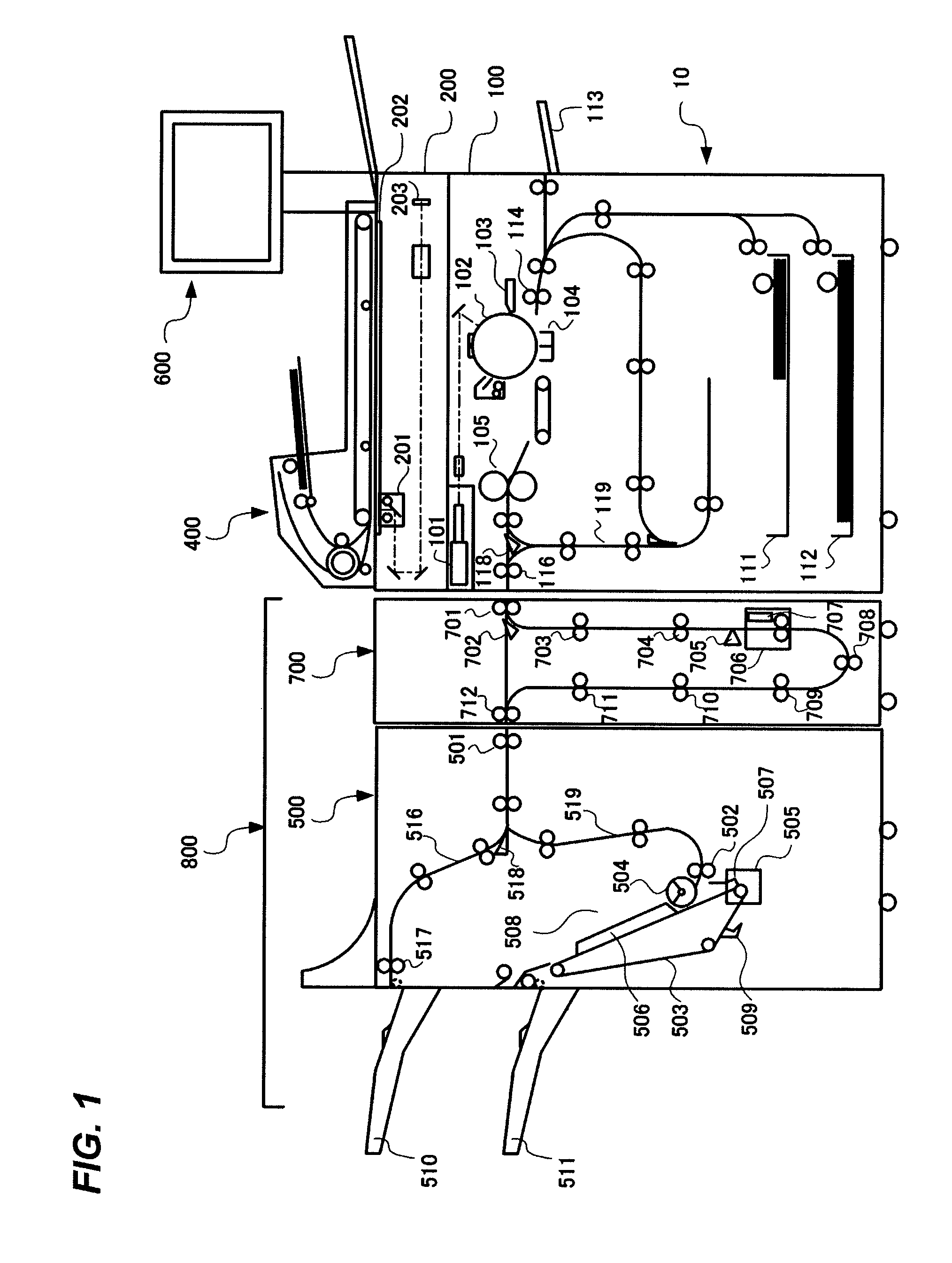
[0027]First, a general configuration of an image forming system constituted with an image forming apparatus main body and a sheet processing apparatus will be described. FIG. 1 is a schematic sectional view illustrating the general configuration of the image forming system.

[0028]As illustrated in FIG. 1, the image forming system is constituted with an image forming apparatus main body 10 and a finisher 800 as the sheet processing apparatus. The image forming apparatus main body 10 includes an image reader 200 to read an image of an original and a printer 100 to record an image on a sheet. Further, the image forming apparatus main body 10 includes an operation displaying portion 600. The finisher 800 is the sheet processing apparatus (i.e., sheet processing ...

second embodiment

[0083]Next, an image forming system constituted with an image forming apparatus main body and a sheet processing apparatus according to a second embodiment will be described. Here, since the general configuration of the image forming system is substantially the same as the abovementioned embodiment, only the sheet discharge control of the finisher will be described in the following.

Sheet Discharge Control of Finisher

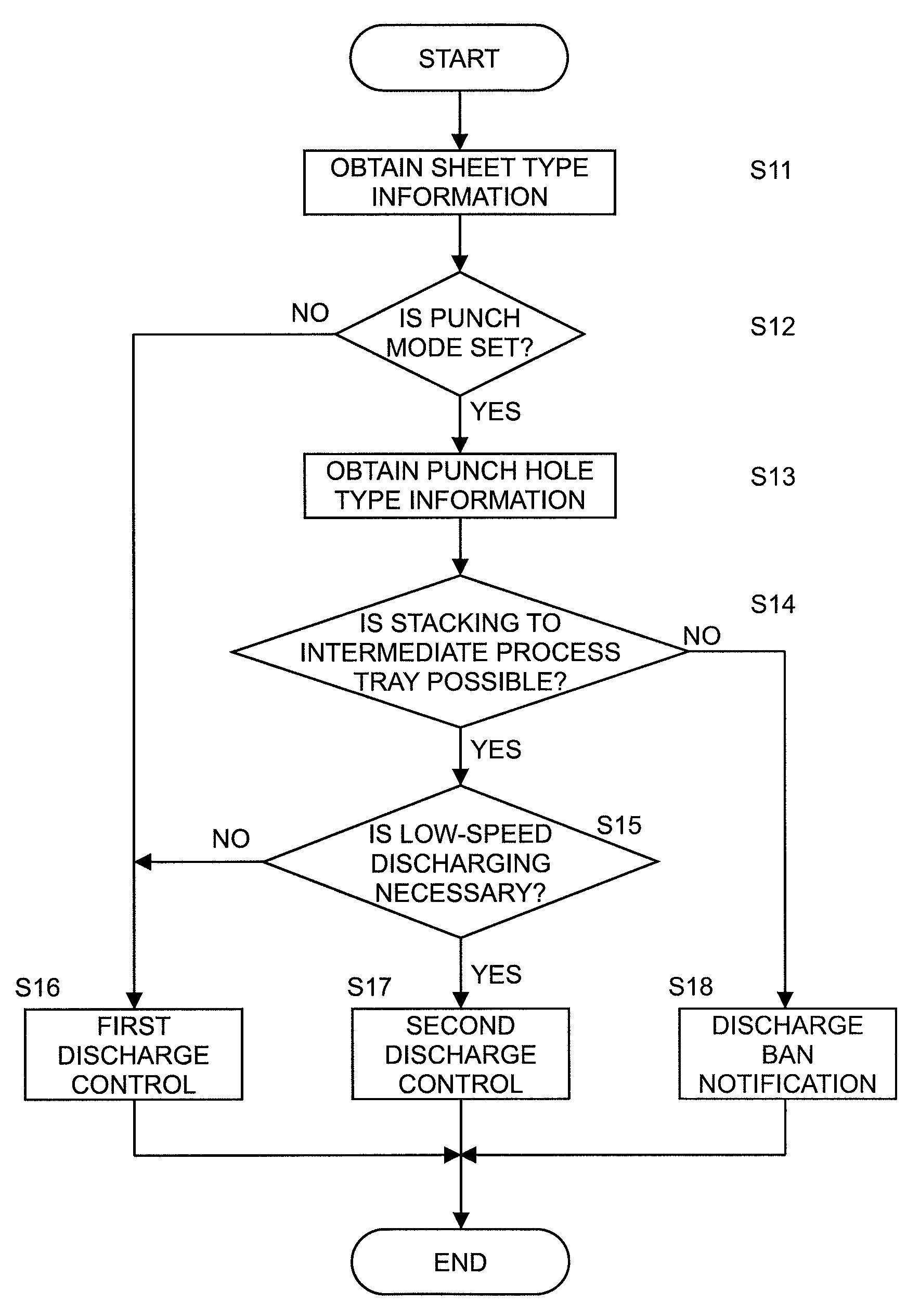
[0084]Next, the sheet discharge control at the finisher 800 will be described with reference to FIGS. 10 and 11. FIG. 10 is a table indicating an example of the sheet discharge control according to the second embodiment. FIG. 11 is a flowchart describing the flow of the sheet discharge control according to the second embodiment.

[0085]In the description of the above embodiment, two sheet discharge controls are performed in accordance with decrease of the strength at the end part of the punch-processed sheet based on the punch process information as an example. In the pres...


PUM

PropertyMeasurementUnit
hole diameteraaaaaaaaaa
lengthaaaaaaaaaa
strengthaaaaaaaaaa

Abstract

A sheet processing apparatus includes a punch portion punching a hole at an end part of a sheet, and a push-out member discharging the sheet by pushing the end part of the sheet where the punch process is performed by the punch portion. The push-out member discharges the sheet at a sheet discharging speed lower than a predetermined speed from the intermediate process tray in accordance with punch process information (i.e., combination of a size and a type of the sheet and number, a shape and a size of holes) that strength of a sheet end part is decreased by the punch process, and is lower than predetermined sheet strength capable of being discharged at the predetermined speed.

Description

BACKGROUND OF THE INVENTION[0001]1. Field of the Invention[0002]The present invention relates to a sheet processing apparatus capable of performing a punch process on a sheet and an image forming system including the sheet processing apparatus.[0003]2. Description of the Related Art[0004]In the related art, there has been proposed a sheet processing apparatus in which sheets respectively having an image formed by an image forming apparatus are conveyed sequentially into an apparatus and a punch process to punch holes can be performed thereon. For example, a sheet processing apparatus on which a punch unit having different number, diameter and position of holes is exchangeably disposed to support a variety of files and rings with a single sheet processing apparatus has been proposed, as disclosed in U.S. Pat. No. 5,746,162.[0005]Further, in the above sheet processing apparatus, punch-processed sheets are eventually discharged to a stack tray while performing a process such as alignin...

Claims


Application Information

Patent Timeline
Patent Type & Authority Patents(United States)
IPC IPC(8): B26D5/00
CPCB26F1/0092G03G15/6552B65H35/0073B26F1/24G03G2215/00751G03G2215/00818G03G2215/00734Y10T83/2094Y10T83/145Y10T83/2022
Inventor WATANABE, NAOTOYAMAUCHI, MANABUFUJII, TAKAYUKIYAMAMOTO, SATORUOKA, YUSHIMIYAKE, TOSHIYUKIYOKOYA, TAKASHINISHIMURA, SHUNSUKEMATSUMOTO, HIDENORI
Owner CANON KK
Why Eureka
Try Eureka