Elastic stabilization system for vertebral columns

a technology of elastic stabilization and vertebral column, which is applied in the field of vertebral column implants, can solve the problems of inability to maintain the flexibility of the rods disposed in pairs, the time and expenditure of the elastic system still exceeds the amount of the implant, and the system works only in flexion (tension) but not in extension (compression)

Active Publication Date: 2013-04-09
ZEHNDER CONSULTING INHABER DR THOMAS ZEHNDER
View PDF22 Cites 0 Cited by
  • Summary
  • Abstract
  • Description
  • Claims
  • Application Information

AI Technical Summary

Benefits of technology

[0019]The vertebral column implant according to the present invention is capable of stabilizing vertebral columns which have become unstable due to degenerative or iatrogenic processes and thus painful, and of reducing or completely avoiding pain. The advantage of an elastic stabilization is above all that individual vertebrae need no longer be fused as previously, which led in many cases to secondary damage to adjacent segments. The particular advantage of the present invention resides in the low production costs, as well as in the simple and safe implantation technique of the system.
resides in the low production costs, as well as in the simple and safe implantation technique of the system.

Problems solved by technology

These recent elastic systems still involve considerable implant time and expenditure.
Although the invention according to patent EP 0498 709 B1 to Graf intends to stabilize elastically, it has the drawback that the system works only in flexion (tension) but not in extension (compression).
However, this invention has the drawbacks that the longitudinal rods have hardly any resistance to buckling and therefore can hardly transmit compressive forces, that the flexibility of the rods disposed in pairs cannot be the same in all directions, and that the transmission of force to the bone screws must take place by means of numerous components.
This invention has the drawbacks, however, that these shock absorbers are not longitudinally adjustable and that the plastic material is passed through a narrow place (neck), which results in a considerable decrease in strength.
However, this invention has the drawbacks that the system is too wide and can be put in place posteriorly only if the pedicles are removed, that it can be used for only one segment, that it cannot, for example, be passed through three screws lying one behind the other and offset, that the bore in the connecting element results in considerable weakening, and that the oval cross-section of the connecting element has only minimum shear strength and minimum resistance to buckling in the anterior / posterior direction.
Furthermore, for fastening the connecting element to the pedicle screw, a locking cap must be used, which is a disadvantage during the operation.
However, this invention has the drawback that the connecting parts are not longitudinally adjustable and cannot be inserted multisegmentally.
This invention has the drawbacks, however, that the system contains an expensive cord band, any desired cushion heights can be achieved only by means of a plurality of standard cushions, variation of the preload on the cord leads to conditions not reproducible biomechanically, and implantation is relatively expensive and takes a long time.

Method used


Image

  • Elastic stabilization system for vertebral columns
  • Elastic stabilization system for vertebral columns
  • Elastic stabilization system for vertebral columns

Examples


Embodiment Construction

[0038]The present invention is described in more detail below with reference to the accompanying drawings, which merely represent examples of embodiments.

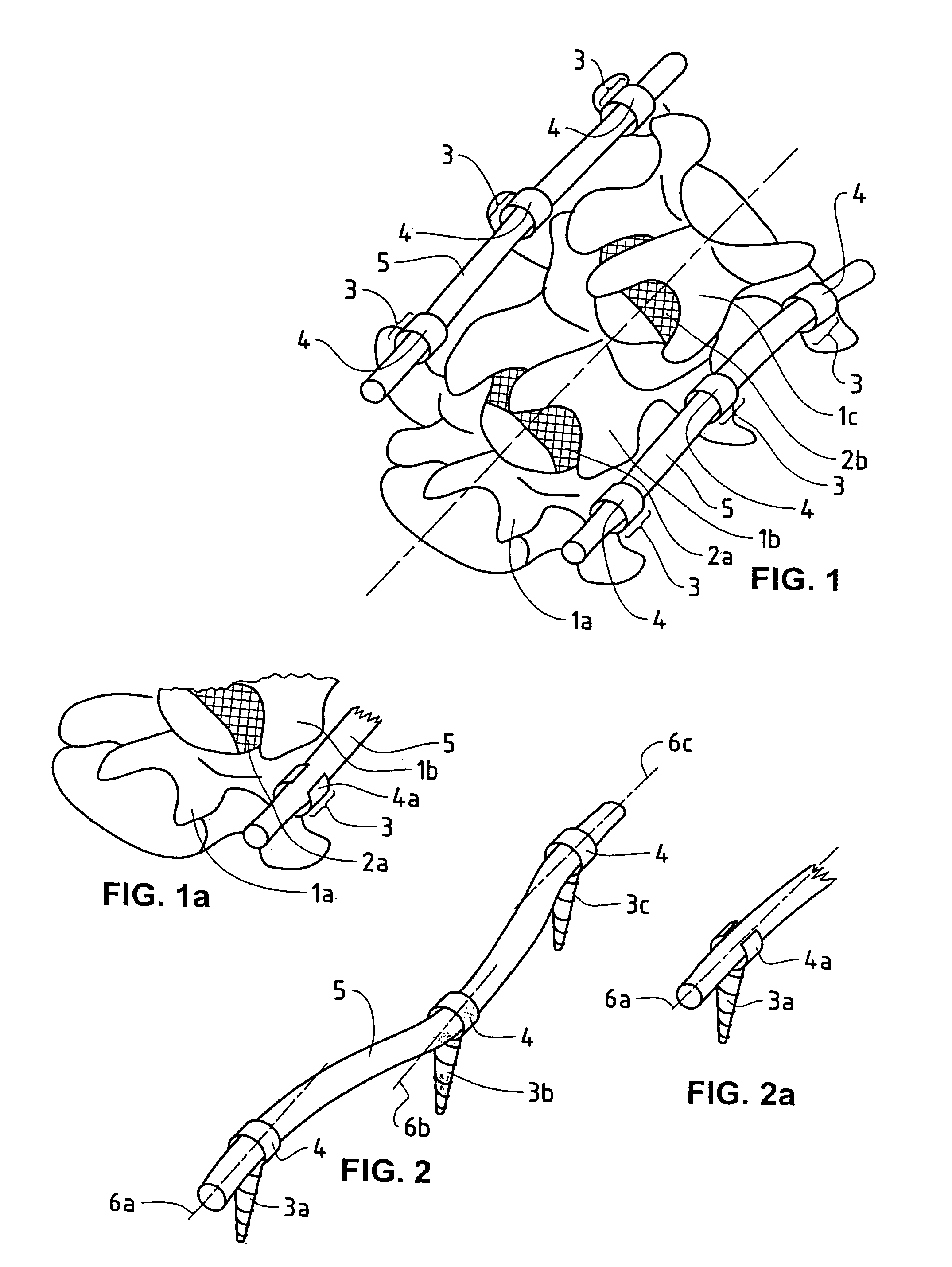
[0039]FIG. 1 shows a vertebral column segment having three vertebrae 1a, 1b, 1c, and two discs 2a, 2b situated between them. Inserted to the left and right of each vertebra is a pedicle screw 3, each having a seat 4 in each of which an elastically bendable, rod-shaped connecting element 5 is fastened to the left and right. The connecting elements 5 are mounted in the seats 4 and serve for flexible stabilization of the vertebrae.

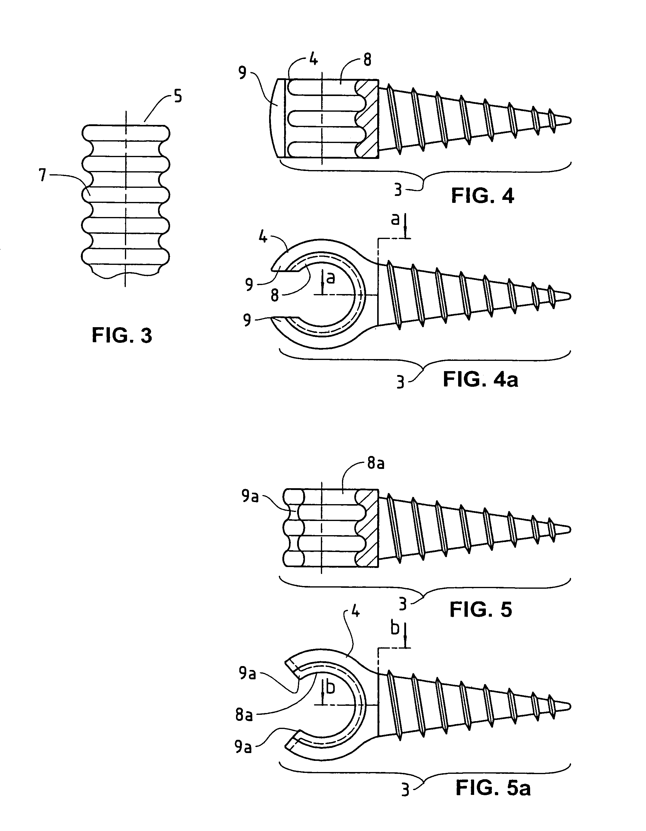
[0040]FIG. 1a is a partial view of an analogous vertebral column segment having a pedicle screw 3 with an open seat 4a for mounting a connecting element 5.

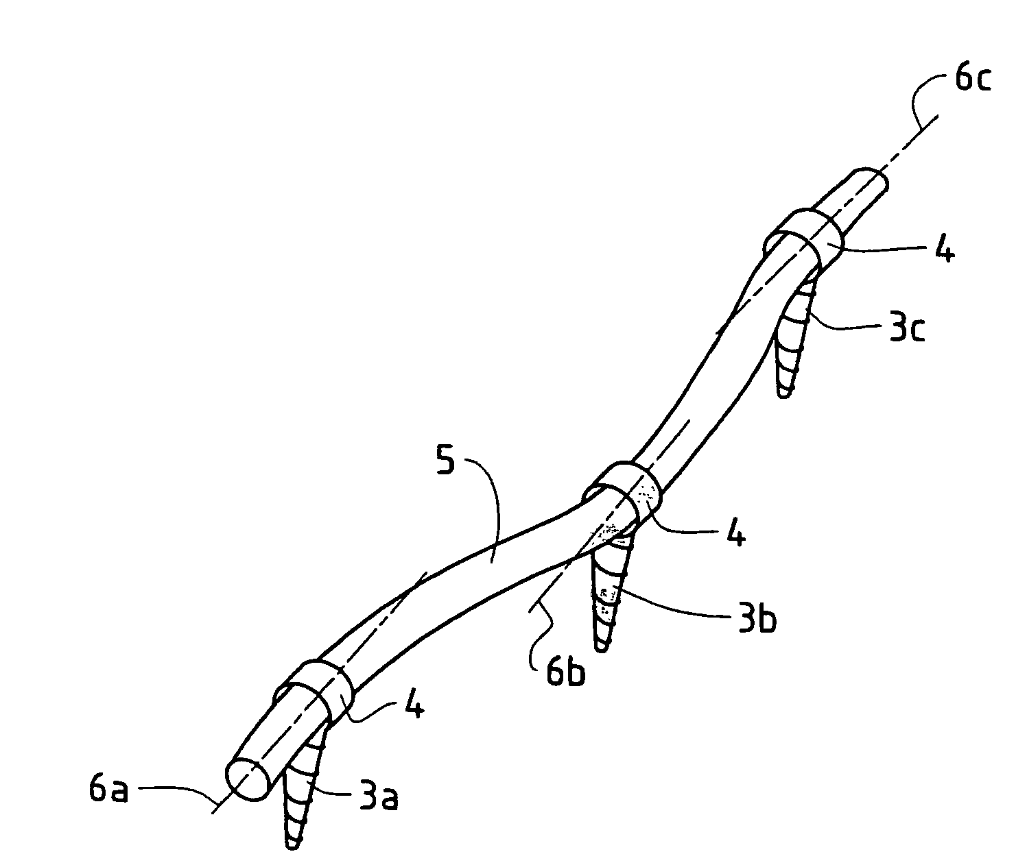
[0041]FIG. 2 shows three pedicle screws 3a, 3b, 3c having mutually offset axes (6a, 6b, 6c) of their seats in the head and the inserted elastically bendable, rod-shaped connecting element 5.

[0042]FIG. 2a shows a partial view corresponding to FIG. 2, but wi...


PUM


Abstract

A vertebral column implant for the elastic stabilization of motion segments including an elastically bendable connecting element which can be passed through the seats of a number of pedicle screws having offset seat axes and be anchored. The connecting element is bendable elastically about every axis of its cross-section in such a way that the connecting element can be passed through, or inserted in, the seats of the screwheads, one behind the other, even when the seats are not situated on one and the same axis.

Description

[0001]This is a divisional application of application Ser. No. 10 / 442,141, filed May 21, 2003, now U.S. Pat. No. 7,125,410.FIELD OF THE INVENTION[0002]The present invention relates to a vertebral column implant of the type comprising a connecting element and a number of bone screws, each having a seat for this connecting element. The implant serves to elastically stabilize the vertebral column of a person having severe back pain.BACKGROUND OF THE INVENTION[0003]The current prior art still comprises mostly stabilization systems aimed at an osseous fusion (stiffening) of affected vertebrae. Elastic systems which merely support and stabilize segments of the vertebral column, but are not supposed to fuse it, have appeared only sporadically so far. These recent elastic systems still involve considerable implant time and expenditure. For reasons of production costs, operating time, and security in handling, future vertebral column stabilization systems should be as simple as possible.[000...

Claims


Application Information

Patent Timeline
Patent Type & Authority Patents(United States)
IPC IPC(8): A61B17/70A61B17/56A61B17/00A61B17/58A61B17/64
CPCA61B17/7005A61B17/701A61B17/7026A61B17/7031A61B17/7032A61B17/6475A61B17/6483A61B17/7004A61B2017/00429
Inventor FREUDIGER, STEFAN
Owner ZEHNDER CONSULTING INHABER DR THOMAS ZEHNDER
Why Eureka
Try Eureka