Elastic stabilization system for vertebral columns

Active Publication Date: 2006-10-24
SPINELAB AG
View PDF14 Cites 260 Cited by
  • Summary
  • Abstract
  • Description
  • Claims
  • Application Information

AI Technical Summary

Problems solved by technology

These recent elastic systems still involve considerable implant time and expenditure.
Although the invention according to patent EP 0498 709 B1 to Graf intends to stabilize elastically, it has the drawback that the system works only in flexion (tension) but not in extension (compression).
However, this invention has the drawbacks that the longitudinal rods have hardly any resistance to buckling and therefore can hardly transmit compressive forces, that the flexibility of the rods disposed in pairs cannot be the same in all directions, and that the transmission of force to the bone screws must take place by means of numerous components.
This invention has the drawbacks, however, that these shock absorbers are not longitudinally adjustable and that the plastic material is passed through a narrow place (neck), which results in a considerable decrease in strength.
However, this invention has the drawbacks that the system is too wide and can be put in place posteriorly only if the pedicles are rem

Method used


Image

  • Elastic stabilization system for vertebral columns
  • Elastic stabilization system for vertebral columns
  • Elastic stabilization system for vertebral columns

Examples


Example

[0036]The present invention is described in more detail below with reference to the accompanying drawings, which merely represent examples of embodiments.

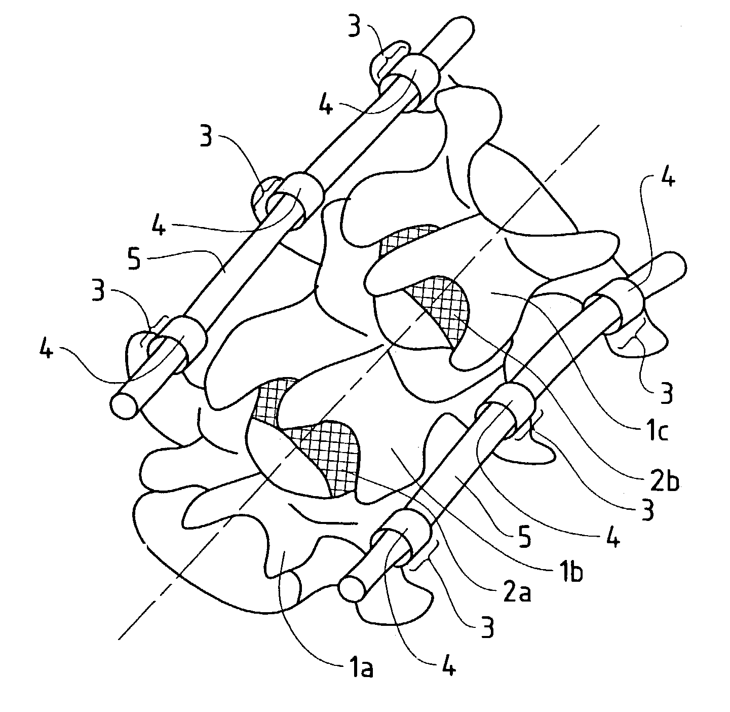
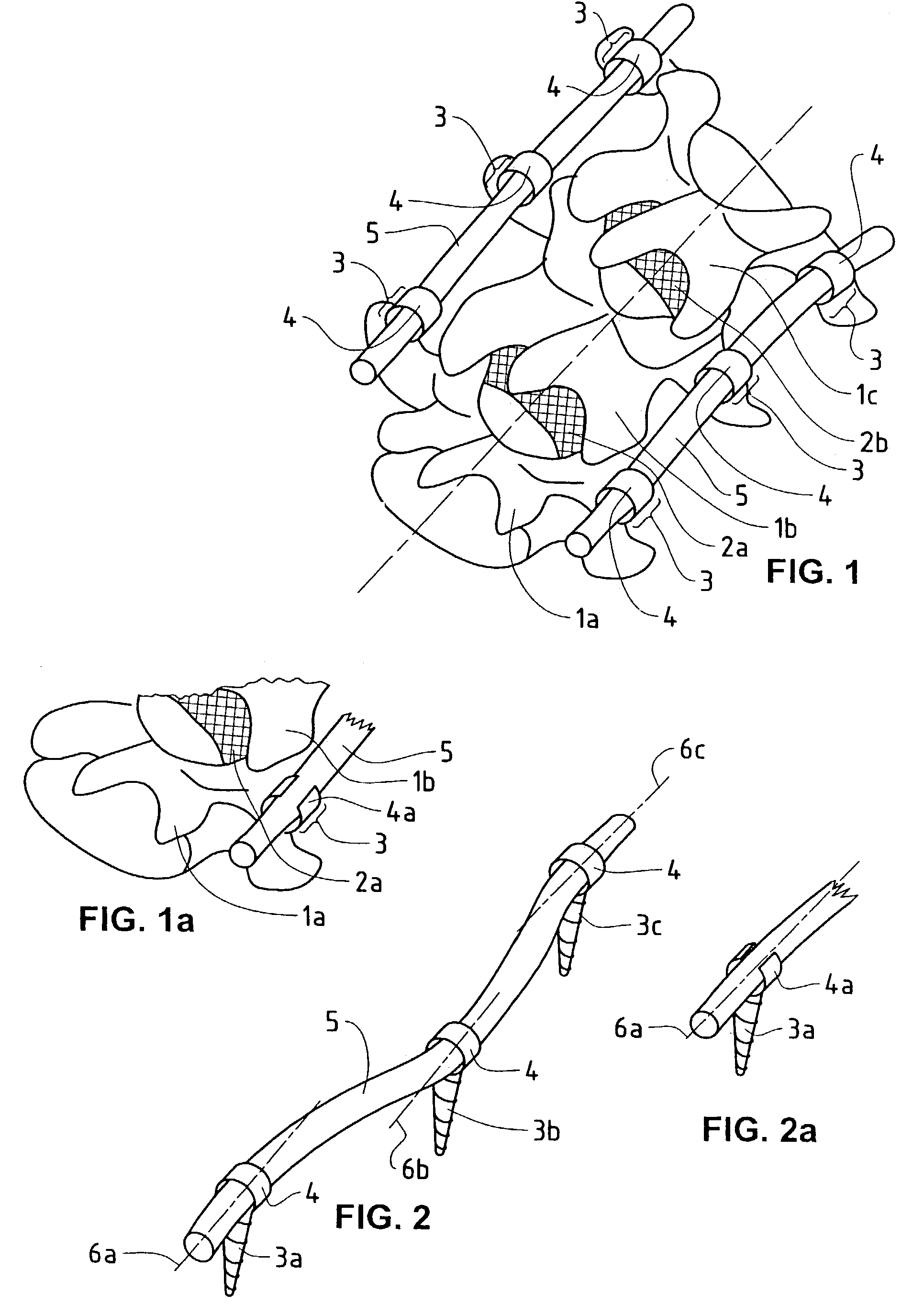
[0037]FIG. 1 shows a vertebral column segment having three vertebrae 1a, 1b, 1c, and two discs 2a, 2b situated between them. Inserted to the left and right of each vertebra is a pedicle screw 3, each having a seat 4 in each of which an elastically bendable, rod-shaped connecting element 5 is fastened to the left and right. The connecting elements 5 are mounted in the seats 4 and serve for flexible stabilization of the vertebrae.

[0038]FIG. 1a is a partial view of an analogous vertebral column segment having a pedicle screw 3 with an open seat 4a for mounting a connecting element 5.

[0039]FIG. 2 shows three pedicle screws 3a, 3b, 3c having mutually offset axes (6a, 6b, 6c) of their seats in the head and the inserted elastically bendable, rod-shaped connecting element 5.

[0040]FIG. 2a shows a partial view corresponding to FIG. 2, but wi...


PUM


Abstract

A vertebral column implant for the elastic stabilization of motion segments (1, 2) comprising an elastically bendable connecting element (5) which can be passed through the seats (4) of a number of pedicle screws (3) having offset seat axes (6a, 6b, 6c) and be anchored. The connecting element is bendable elastically about every axis of its cross-section in such a way that the connecting element can be passed through, or inserted in, the seats of the screwheads, one behind the other, even when the seats are not situated on one and the same axis. The connecting element and the seat in the screwhead each have wholly, or in part, a structured surface, in such a way that the structured surface of the seat engages the structured surface of the connecting element, and shifting can be prevented in assembled condition.

Description

FIELD OF THE INVENTION[0001]The present invention relates to a vertebral column implant of the type comprising a connecting element and a number of bone screws, each having a seat for this connecting element. The implant serves to elastically stabilize the vertebral column of a person having severe back pain.DESCRIPTION OF THE RELATED ART[0002]The current prior art still comprises mostly stabilization systems aimed at an osseous fusion (stiffening) of affected vertebrae. Elastic systems which merely support and stabilize segments of the vertebral column, but are not supposed to fuse it, have appeared only sporadically so far. These recent elastic systems still involve considerable implant time and expenditure. For reasons of production costs, operating time, and security in handling, future vertebral column stabilization systems should be as simple as possible.[0003]The advantages of elastic stabilizations are becoming increasingly well known, above all by young patients, so that va...

Claims


Application Information

Patent Timeline
IPC IPC(8): A61B17/56A61B17/00A61B17/58A61B17/64A61B17/70
CPCA61B17/7005A61B17/701A61B17/7026A61B17/7031A61B17/7032A61B17/6475A61B17/6483A61B17/7004A61B2017/00429
Inventor FREUDIGER, STEFAN
Owner SPINELAB AG
Why Eureka
Try Eureka