Vehicle door structure and method for fabricating the same

a technology for vehicle doors and doors, applied in the field of vehicle door structures, can solve the problems of undesirable increase in material inability to absorb the energy of side impact of side impact in a favorable manner, and favorable transmission of crash load, so as to reduce the cost and weight of door beams, absorb energy, and facilitate the transmission of crash load

Active Publication Date: 2013-04-16
HONDA MOTOR CO LTD
View PDF67 Cites 10 Cited by
  • Summary
  • Abstract
  • Description
  • Claims
  • Application Information

AI Technical Summary

Benefits of technology

[0008]In view of such problems of the prior art, a primary object of the present invention is thus to minimize the cost and weight of a door beam for a vehicle door structure, achieve a favorable transmission of a crash load at the time of a frontal crash, and adequately absorb energy at the time of a side crash.
[0009]A second object of the present invention is to provide a vehicle door structure which is effective in dealing with a frontal, side or rear crash in a both effective and economical manner.
[0012]In particular, if the cross section is provided with a S-shaped cross section, the beam member, not having a closed cross section, is enabled to favorably absorb an impact load of a side crash. More specifically, because the beam member is provided with a S-shaped cross section instead of forming a double walled structure or a box-shaped structure jointly with the inner panel, the beam member is enabled to completely collapse without leaving any un-collapsed part by a crash load of a side crash, and this ensures a favorable absorption of energy at the time of a side crash. Also, the beam member and inner panel do not redundantly overlap each other, and this allows the cost and weight to be reduced.
[0015]If the vehicle door structure comprises an inner cover panel extending vertically as an upper extension of the inner panel between a lower edge and an upper edge of the S-shaped cross section on an inboard side of the S-shaped cross section, the number of component parts can be reduced, and this contributes to the reduction in the manufacturing and material costs.
[0016]According to another embodiment of the present invention, the S-shaped cross section part is formed with an access opening confined within a vertically extending part of the cross section. Such an access opening can be conveniently used, for example, for providing an access that is required for mounting a door mirror to the outer panel.
[0017]If such an opening overlaps with a ridge line of the beam member, the capability of the beam member to transmit and support a fore-and-aft load may be diminished. Therefore, it is desirable that at least the vertically extending part of the beam member in which the opening is formed is vertically more elongated than another, substantially coplanar part of the beam member adjacent thereto along the fore-and-aft direction, so that the access opening may be confined within the vertically extending part of the beam member or, in other words, the vertically extending part of the beam member is vertically wide (tall) enough to accommodate an access opening of a required size. Preferably, the access opening is does not cross any of the ridge lines, so that the access opening does not compromise the functioning of the beam member as a load path member.

Problems solved by technology

Therefore, when the size of the door beam is significant, the material cost and weight of the door beam may undesirably increase.
However, because the centroid given as a point where a geometrical moment of area becomes zero does not coincide with the direction of the force acting upon the door beam, the impact load of a frontal crash applies a bending moment to the door beam, and such a bending of the door beam prevents a favorable transmission of the crash load (load path) to a rear part of the vehicle body.
However, such a door beam does not so readily deform as a channel member when subjected to a lateral force, and is therefore unable to absorb the energy of a side impact of a side crash in a favorable manner.
Also, in either case, if the door beam is simply attached to the inner panel, the fore-and-aft axial load that acts upon the door at the time of a frontal crash is offset from the centroid of the cross section, and the efficiency of transmitting the fore-and-aft axial force is thereby impaired.
The conventional door beams including those using a steel channel member tends to be incompletely collapsed, and the energy of a side crash cannot be absorbed so much as desired.

Method used


Image

  • Vehicle door structure and method for fabricating the same
  • Vehicle door structure and method for fabricating the same
  • Vehicle door structure and method for fabricating the same

Examples


first embodiment

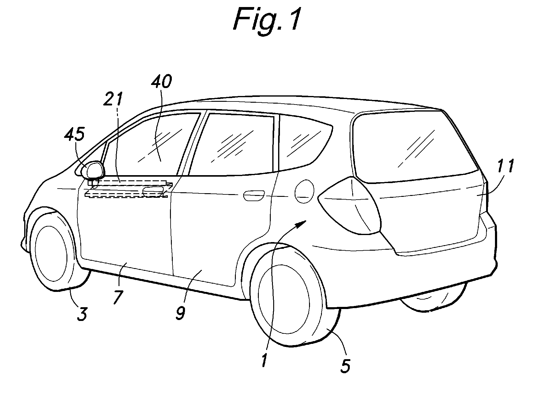
[0033]the vehicle door structure of the present invention is described in the following with reference to FIGS. 1 to 6.

[0034]FIG. 1 shows a vehicle to which the vehicle door structure of the present invention is applied. In FIG. 1, numeral 1 denotes a vehicle body as a whole, numeral 3 front wheels, numeral 5 rear wheels, numeral 9 rear side doors, and 11 a tailgate.

[0035]The vehicle body structure of the present invention may be applied to any or all of the front side doors 7 and rear side doors 9. In the illustrated embodiment, the vehicle body structure of the present invention is applied to the left front door.

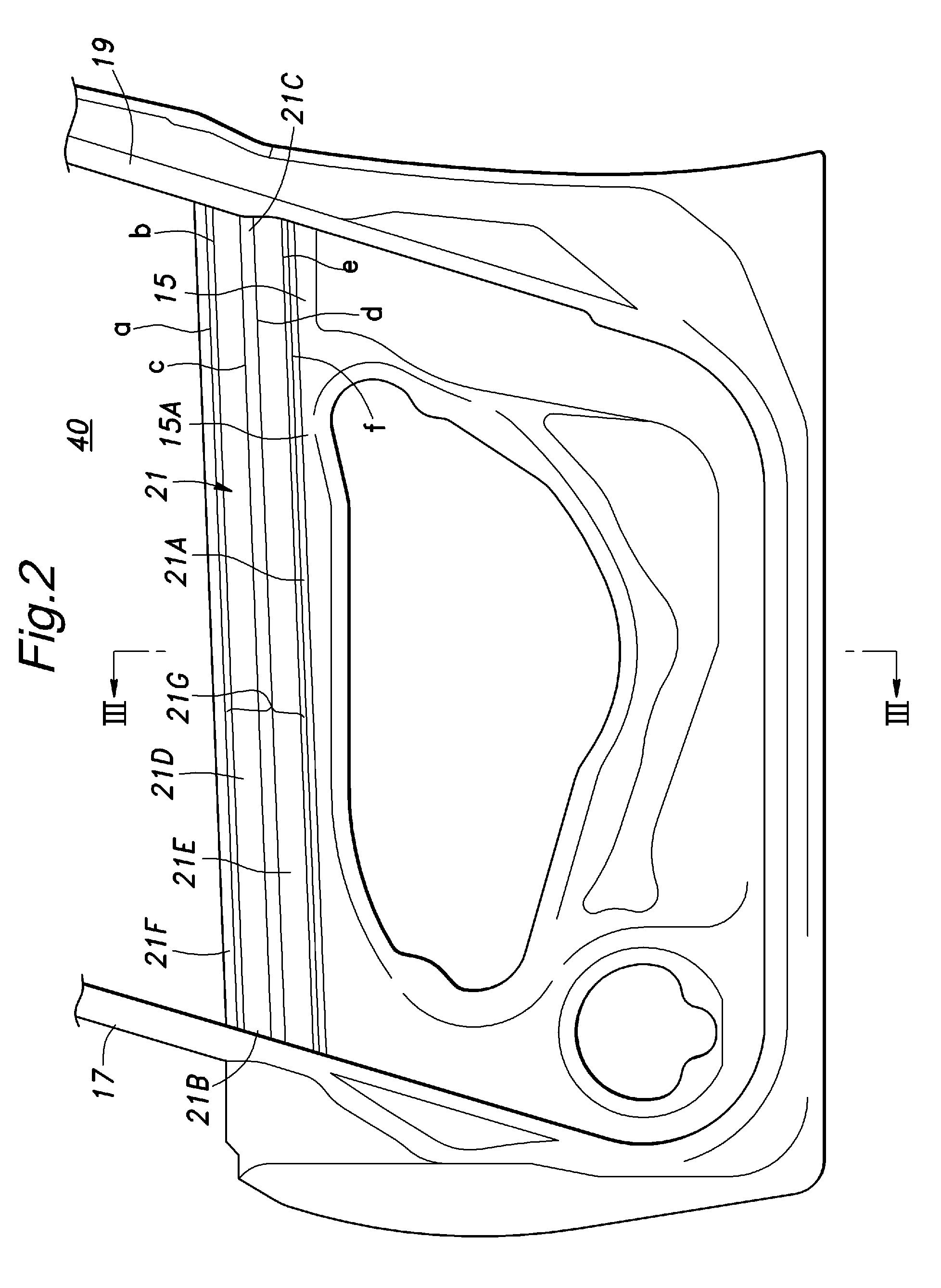
[0036]As shown in FIGS. 2 to 6, the front side door 7 comprises an outboard outer panel 13 and inboard inner panel 15. The space between the outer panel 13 and inner panel 15 receives a side window glass panel 31 in a vertically slidable manner.

[0037]The inner panel 15 is attached to an A-pillar 35 via a door hinge 33. The A-pillar 35 is connected to a front upper member 3...

second embodiment

[0050]FIG. 7 shows the present invention. In FIG. 7, the parts corresponding to those of the previous embodiment are denoted with like numerals without repeating the description of such parts. In this embodiment, an inner cover panel 24 having a hat-shaped cross section is attached to an inner surface of the beam member 21. More specifically, the inner cover panel 24 is provided with an upper flange that overlaps with the upper flat plate part 21F of the beam member 21 and a lower flange that overlaps with both the upper flange 15A of the inner panel 15 and lower flat plate part 21A of the beam member 21. The inner cover panel 24 may be made of steel sheet similar to the material of the remaining part of the door. In such a case, the overlapping parts are typically MIG welded, spot welded or otherwise bonded to each other. If desired, the inner cover panel 24 may also be made of other materials that provide a required mechanical strength and rigidity.

[0051]Thus, the beam member 21 a...

fourth embodiment

[0053]FIGS. 9 to 11 show the vehicle door structure according to the present invention. In FIGS. 9 to 11, the parts corresponding to those of the previous embodiments are denoted with like numerals without repeating the description of such parts.

[0054]The S-shaped cross section part 21G of the beam member 21, in particular the bottom wall of the channel member 21D is given with a locally (with respect to the fore-and-aft direction) enlarged vertical dimension or width h such as a vertically elongated part 22 formed in a front part of the beam member 21 of the illustrated embodiment. The vertically elongated part 22 is formed with an access opening 23 for assembly work.

[0055]The access opening 23 provides an access to the outer panel 13 of the front side door 7 from an inboard side when attaching a side mirror or door mirror 45 (see FIG. 1) to the outer panel 13 in a skin mount arrangement. The access opening 22 is formed in the vertically elongated part 22 without crossing any of th...


PUM


Abstract

In a vehicle door structure, a beam member (21) having a S-shaped cross section and extending in a fore-and-aft direction of a vehicle body is attached to an inner panel (15), and the upper edge of the inner panel (15) is formed by the beam member (21). Thereby, a crash load of a frontal crash is transmitted in a favorable manner, and energy of a side impact is adequately absorbed without incurring a cost increase or a weight increase owing to the use of the door beam.

Description

TECHNICAL FIELD[0001]The present invention relates to a vehicle door structure and a method for fabricating the same, and in particular to a vehicle door structure which is made resistant to front, rear and side crashes and a method for fabricating the same.BACKGROUND OF THE INVENTION[0002]A vehicle door structure used as a side door of a motor vehicle is formed of an outboard outer panel and an inboard inner panel. For reinforcement, a door structure is typically fitted with a reinforcement beam called as door beam having a front and rear end connected to the front and rear part of the inner panel, respectively. There are various forms of door beams, and they include those using a steel channel member that forms a box-shaped cross section in cooperation with the inner panel, those using a double-hat shaped cross section and those using a pipe member. See Japanese patent No. 3989373, and Japanese patent laid open publications No. 2005-126018 and No. 2006-021744.[0003]A door beam hav...

Claims


Application Information

Patent Timeline
Patent Type & Authority Patents(United States)
IPC IPC(8): B60J5/04E06B3/34
CPCB60J5/0426B60J5/0444
Inventor YASUHARA, SHIGETOSEGAWA, SHINGOHORINO, MASATOSHIKOMINAMIDATE, MASAMI
Owner HONDA MOTOR CO LTD
Why Eureka
Try Eureka