
Mobile tire inflator

a technology of inflator and tire, which is applied in the field of tire inflator, can solve the problems of tire over-inflated or under-inflated, inconvenient operation, and user's inability to know the current tire pressure of the tire, and achieve the effects of high mobility, convenient operation and convenient us

Active Publication Date: 2013-04-16
HUANG RAYMOND
View PDF13 Cites 8 Cited by
  • Summary
  • Abstract
  • Description
  • Claims
  • Application Information

AI Technical Summary

Benefits of technology

[0007]The present invention has been accomplished under the circumstances in view. It is the main object of the present invention to provide a mobile tire inflator, which has the advantages of operation flexibility, high mobility and ease of use.

Problems solved by technology

This operation is inconvenient.
Thus, the user cannot know the current tire pressure of the tire and the tire may be over-inflated or under-inflated.
However, the aforesaid fixed type of automatic tire inflator is huge and heavy, and cannot be carried by the user.
It can only be set in a fixed place (for example, gas station) for regular use, not practical to fit different needs.
Further, the aforesaid fixed type of automatic tire inflator simply provides an automatic inflation mode, giving no flexibility in use.
Further, tire pressure display and add / deduct functions are designed at the face panel of the fixed type of automatic tire inflator that is disposed far away from the user, making the operation inconvenient.

Method used


Image

  • Mobile tire inflator
  • Mobile tire inflator
  • Mobile tire inflator

Examples


Embodiment Construction

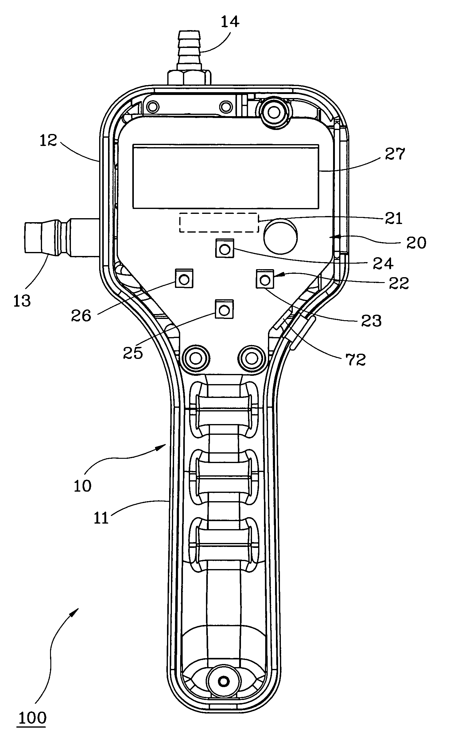
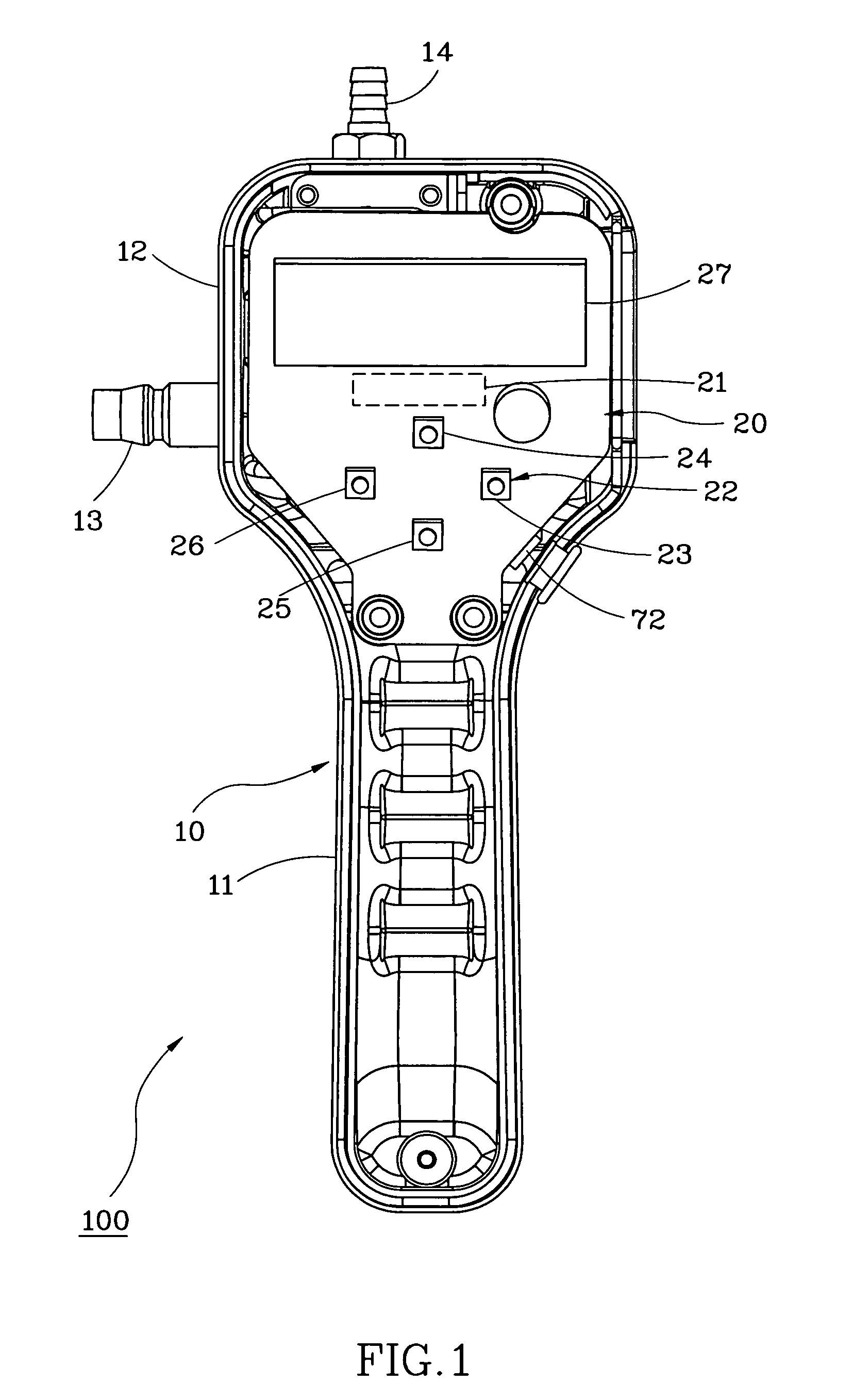
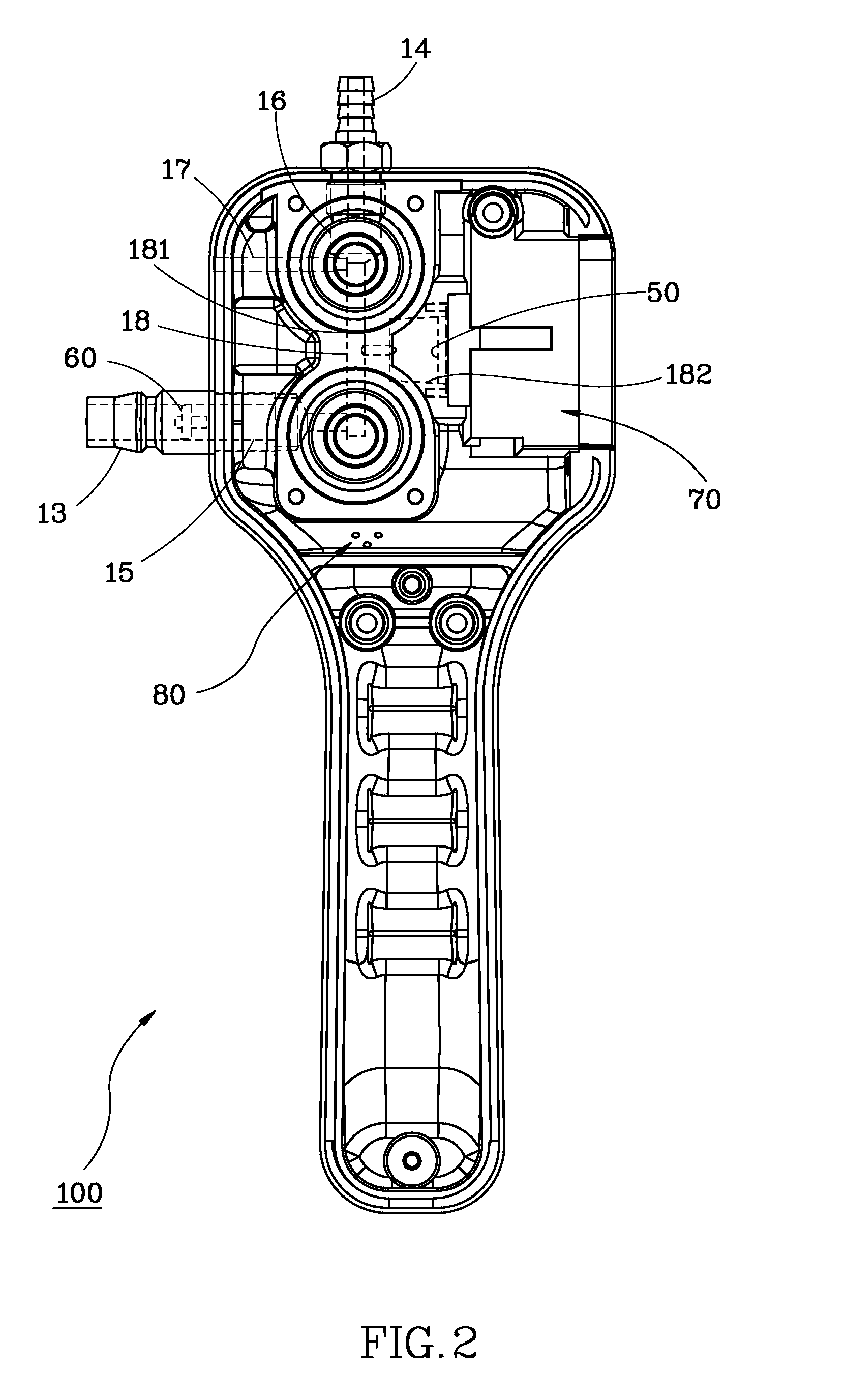
[0012]Referring to FIGS. 1˜3, a mobile tire inflator 100 in accordance with the present invention is shown comprising a housing 10, a control panel 20, an inflation valve 30, a discharge valve 40, a pressure sensor 50, a check valve 60, a power supply unit 70 and a speaker 80.

[0013]The housing 10 includes a handle 11 and a head 12. The handle 11 is configured for grasping thereof by a person's hand. The head 12 has an air intake pipe 13 located on the periphery for the connection of an external air pressure source (not shown; for example, air compressor), an air outlet pipe 14 located on the periphery for connecting to a tire's air valve (not shown), an air intake passage 15 and an air outlet passage 16 defined therein and respectively connected to the air intake pipe 13 and the air outlet pipe 14, an air discharge passage 17, and a main air passage 18 in communication with the air intake passage 15, the air outlet passage 16 and the air discharge passage 17. The air discharge passa...


PUM


Abstract

A mobile tire inflator includes a control panel, multiple air passages, an inflation valve, a discharge valve and a pressure sensor. The user can control the operation of the inflation valve and the discharge valve automatically or manually by through a control panel, and switch between the automatic mode and the manual mode during operation. Matching with the operation of the pressure sensor, the mobile tire inflator achieves accurate tire pressure inflation and discharge and has the advantages of operation flexibility and high mobility.

Description

BACKGROUND OF THE INVENTION[0001]1. Field of the Invention[0002]The present invention relates to tire inflators and more particularly, to a mobile tire inflator.[0003]2. Description of the Related Art[0004]Conventionally, a tire inflator must be continuously pushed and pulled to inflate a tire to a saturated condition. This operation is inconvenient. Further, when inflating the tire, the tire pressure value is displayed at the end of air pressure source (for example, the pressure gauge of the air compressor). Thus, the user cannot know the current tire pressure of the tire and the tire may be over-inflated or under-inflated.[0005]In view of the aforesaid drawbacks, a fixed type of automatic tire inflator was created. During the use of this fixed type of automatic tire inflator, attach the air tube of the fixed type of automatic tire inflator to the air valve of the tire and then operate the face panel of the fixed type of automatic tire inflator to input a target tire pressure. At t...

Claims


Application Information

Patent Timeline
Patent Type & Authority Patents(United States)
IPC IPC(8): F16K15/20
CPCB60S5/046Y10T137/3662Y10T137/36Y10T137/8326
Inventor HUANG, RAYMOND
Owner HUANG RAYMOND
Learn More