Liquid ejection head and manufacturing method therefor

a technology of liquid ejection and manufacturing method, which is applied in the direction of metal-working equipment, printing, writing implements, etc., can solve the problems of difficult to remove the stop layer from the front surface side, difficult to handle and dangerous apparatus, and inability to easily substitute liquid and gas

Active Publication Date: 2013-04-16
CANON KK
View PDF6 Cites 1 Cited by
  • Summary
  • Abstract
  • Description
  • Claims
  • Application Information

AI Technical Summary

Benefits of technology

[0010]Therefore, it is an object of the present invention to provide a manufacturing method of a liquid ejection head which includes a liquid supply port into which liquid can be caused to flow satisfactorily.

Problems solved by technology

In the ink jet recording head, a flow path forming member is formed on a front surface side of the substrate, and hence, in some cases, it is difficult to remove the stop layer from the front surface side.
This apparatus is difficult to handle and dangerous in some cases.
When a liquid film (hereinafter, referred to as a meniscus) is formed at the protruding portions of the scallop pattern, substitution of liquid and gas cannot be easily progressed, and in some of the supply ports, the removal liquid cannot reach the stop layer.
Therefore, in some cases, fluctuations in removal of the stop layer occur.
The fluctuations in removal of the stop layer lead to reduction in reliability.
As described above, there is a case where a usable range may be limited in terms of design and materials.

Method used


Image

  • Liquid ejection head and manufacturing method therefor
  • Liquid ejection head and manufacturing method therefor
  • Liquid ejection head and manufacturing method therefor

Examples


example 1

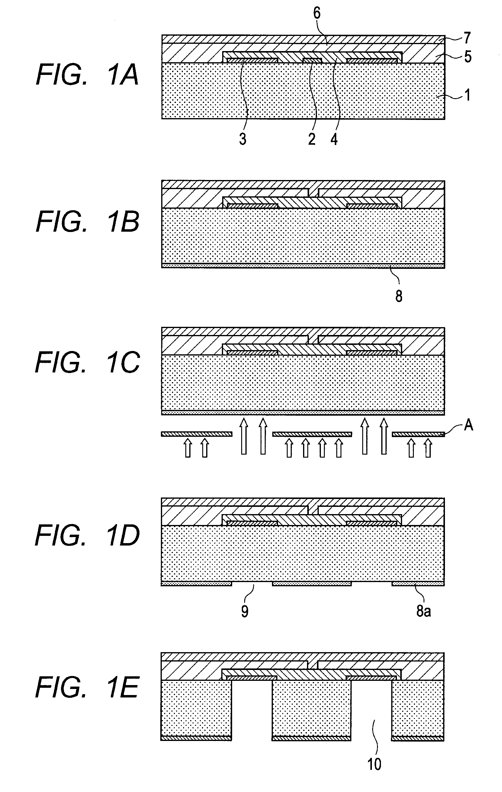
[0070]In this example, with the manufacturing method of an ink jet recording head illustrated in FIGS. 1A to 1E, the ink jet recording head was manufactured.

[0071]First, as the substrate 1, a silicon substrate was prepared, on which the energy generating element for causing ejection of ink, a driver, and a logic circuit were formed. On this substrate, an Al film as the stop layer 3 was formed.

[0072]Next, on the surface of the substrate 1, the flow path mold member 3 as a mold of the ink flow path was formed by a mold injection method.

[0073]Next, on the rear surface of the substrate 1, a photosensitive resin as the etch resistant film 8 was formed by spin coating. As the photosensitive resin, AZ-P4620 (trade name, manufactured by AZ Electronic Materials Ltd.) was used.

[0074]Next, exposure processing was performed to the photosensitive resin with the use of an exposure machine manufactured by EV group Inc., at an exposure amount of 1,000 mJ / cm2 through the photomask A having the patte...

example 2

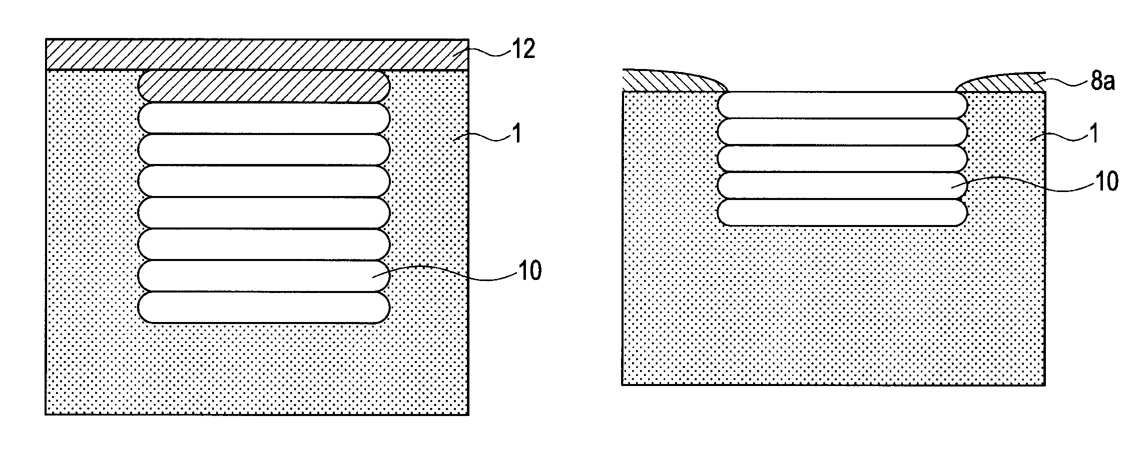
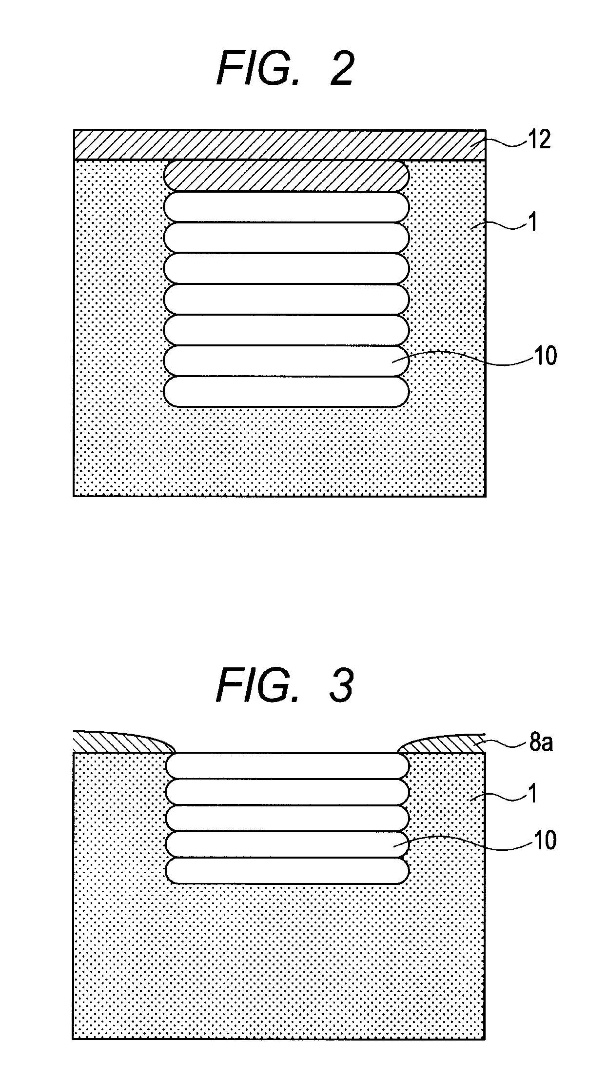
[0080]In this example, when the exposure processing is performed in order to form the opening pattern for the ink supply port in the etch resistant film, exposure was performed under a state in which the mask was raised from the focus position by 30 μm. Further, the heating processing after the opening pattern formation was not performed. Except for the above-mentioned points, the same steps as those in Example 1 were used to manufacture the ink jet recording head.

[0081]In the wall surface of the ink supply port formed in this example, multiple groove shapes were formed from the opening surface in the direction perpendicular to the surface direction. Long grooves among the groove shapes had a length of 30 μm or more.

[0082]By removing the stop layer formed of the Al film with the use of the removal liquid supplied from the ink supply port, the stop layer was able to be removed in a short time period with good yield.


PUM

PropertyMeasurementUnit
lengthaaaaaaaaaa
depthaaaaaaaaaa
sizeaaaaaaaaaa

Abstract

Provided is a liquid ejection head including a substrate including a liquid supply port and an energy generating element, in which the liquid supply port has at least one groove shape formed in a wall surface thereof, the at least one groove shape extending from a rear surface, which is a surface opposite to a front surface on which the energy generating element is formed, toward the front surface.

Description

BACKGROUND OF THE INVENTION[0001]1. Field of the Invention[0002]The present invention relates to a liquid ejection head for ejecting liquid and a manufacturing method therefor.[0003]2. Description of the Related Art[0004]As a method of forming ink supply ports in an ink jet recording head, as described in Japanese Patent Application Laid-Open No. 2006-130868, there is a method of forming the ink supply ports by using dry etching from a rear surface of a substrate. In a case of a product such as the ink jet recording head, in which many ink supply ports are formed in a wafer, by using dry etching to form the ink supply ports, it is possible to suppress increase in opening width of the ink supply ports.[0005]In order to form the ink supply port in the substrate to have a shape perpendicular to a surface direction, as described in Japanese Patent Application Laid-Open No. 2003-053979, a Bosch™ process is generally used, which performs coating and etching alternately. For example, by de...

Claims


Application Information

Patent Timeline
Patent Type & Authority Patents(United States)
IPC IPC(8): B41J2/04
CPCB41J2/1603B41J2/1628B41J2/1645B41J2/1631Y10T29/49401
Inventor OKANO, AKIHIKOKUBOTA, MASAHIKOKANRI, RYOJIFUKUMOTO, YOSHIYUKIMORISUE, MASAFUMI
Owner CANON KK
Why Eureka
Try Eureka