Pump device for pumping blood

Pending Publication Date: 2022-03-10
TERUMO KK
View PDF0 Cites 1 Cited by
  • Summary
  • Abstract
  • Description
  • Claims
  • Application Information

AI Technical Summary

Benefits of technology

The present invention provides a pump device that can make a fluid flow smoothly by reducing shear stress. The pump device includes an impeller and a housing with a movable sleeve and a fixed surface that form a hydrodynamic gap. The gap between the two surfaces increases when the impeller rotates, allowing the fluid to flow through without being obstructed. This reduces the risk of damage to the fluid, such as hemolysis, which can occur when there is too much shear stress. The pump device is simple in design and can be used to pump blood from the body without causing damage.

Problems solved by technology

Such an increase in shear stress tends to increase hemolysis of blood.

Method used


Image

  • Pump device for pumping blood
  • Pump device for pumping blood
  • Pump device for pumping blood

Examples


Embodiment Construction

[0019]Preferred embodiments of the present invention will hereinafter be described in detail with reference to the accompanying drawings.

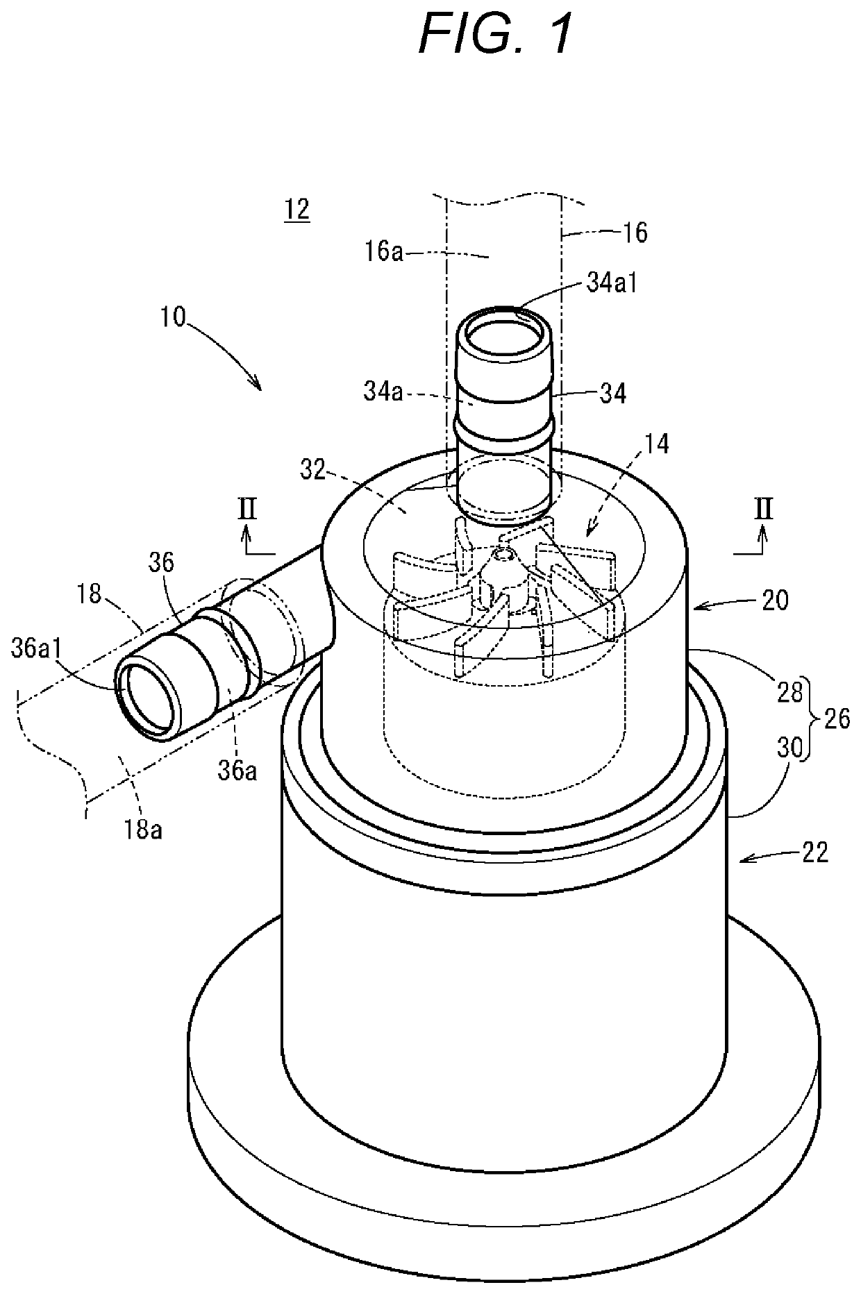
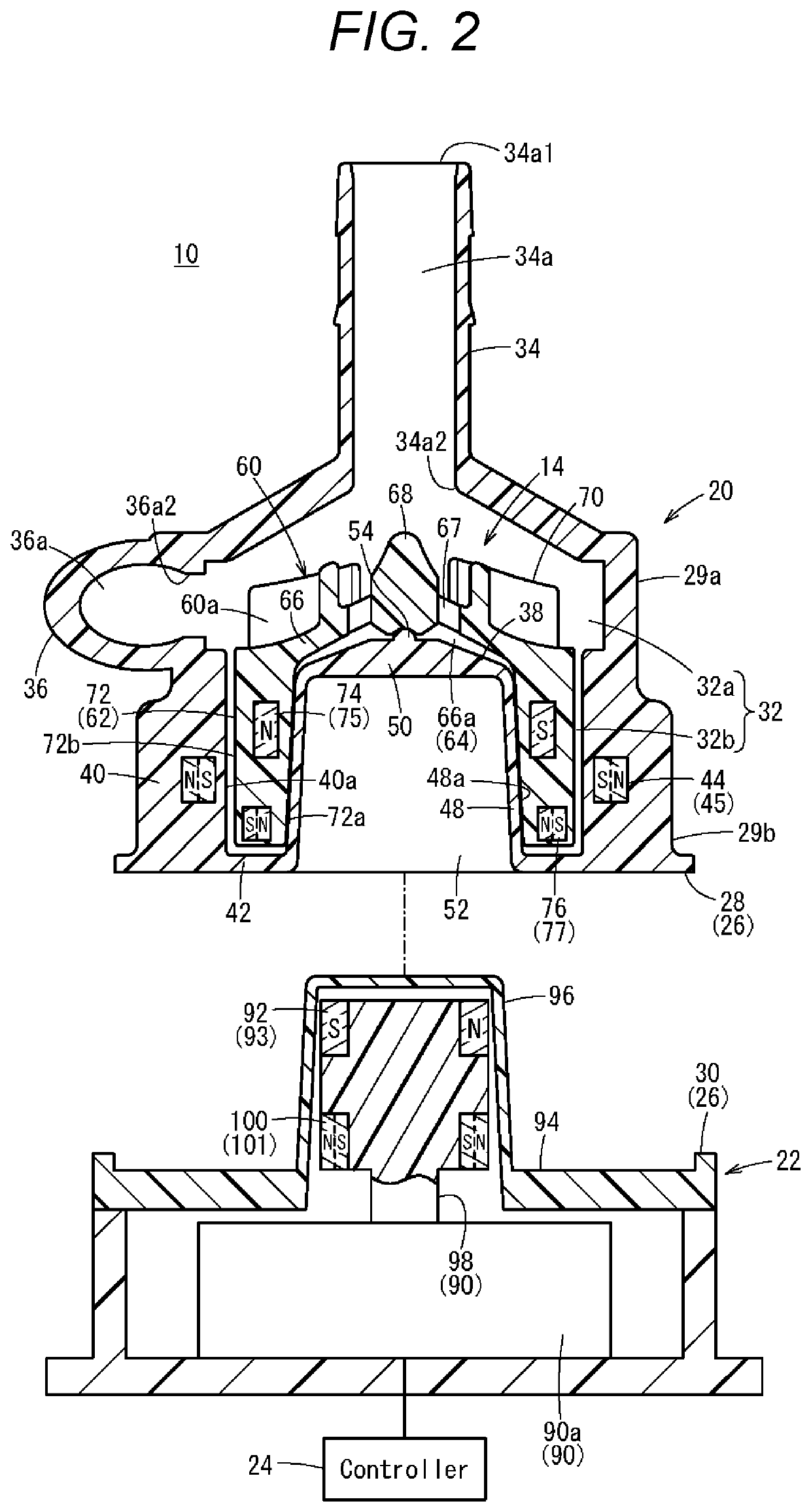
[0020]A pump device 10 according to an embodiment of the present invention is used as a power source of a heart-lung machine 12 that assists the cardiopulmonary function of a patient (or substitutes for the heart and lungs). The pump device 10 takes blood out of the patient's body and pumps blood into the body. As shown in FIG. 1, the pump device 10 is a centrifugal pump having an impeller 14 disposed inside the device and is configured to allow a fluid to flow by a centrifugal force associated with rotation of the impeller 14.

[0021]In the heart-lung machine 12, a removal tube 16 including a removal lumen 16a and a delivery tube 18 including a delivery lumen 18a are connected to the pump device 10, thereby forming a circulation circuit for blood circulation between a patient and the machine. In assembling the heart-lung machine 12, the tip opening ...


PUM


Abstract

A pump device includes an impeller and a housing that houses the impeller in a rotatable manner. The impeller includes a fin (vane) unit and a movable sleeve. The housing includes a fixed sleeve that houses the movable sleeve. A first gap is formed between an inner periphery of the movable sleeve and an opposing surface that faces the inner periphery. Since the inner periphery and the opposing surface are inclined relative to an axis of the impeller, the first gap is increased when the impeller ascends with rotation of the impeller.

Description

CROSS REFERENCE TO RELATED APPLICATIONS[0001]This application is a continuation of PCT Application No. PCT / JP2020 / 011198, filed Mar. 13, 2020, based on and claiming priority to Japanese Application No. 2019-113877, filed Jun. 19, 2019, both of which are incorporated herein by reference in their entirety.BACKGROUND OF THE INVENTION[0002]The present invention relates to a pump device that causes a fluid to flow.[0003]In a heart-lung machine that causes blood (fluid) of a patient to flow, a pump device is used as a power source for blood circulation. For example, U.S. Pat. No. 9,068,572 issued to Ozaki et al. discloses a centrifugal pump device configured to rotate an impeller disposed inside a housing so as to draw blood into the housing by a centrifugal force associated with the rotation of the impeller and to discharge the blood from the housing.[0004]In the pump device disclosed in U.S. Pat. No. 9,068,572, magnetic coupling is formed between a motor chamber and the impeller, and th...

Claims


Application Information

Patent Timeline
IPC IPC(8): A61M60/232A61M60/419A61M60/824A61M60/148
CPCA61M60/232A61M60/148A61M60/824A61M60/419F04D29/047F16C32/04F04D29/048F16C17/10F04D13/02F04D13/06A61M60/38A61M60/109
Inventor MORI, TAKEHISA
Owner TERUMO KK
Why Eureka
Try Eureka