Compact, two stage, zero flux electronically compensated current or voltage transducer employing dual magnetic cores having substantially dissimilar magnetic characteristics

a current or voltage transducer, two-stage technology, applied in the direction of instruments, dynamo-electric motor meters, inductances, etc., can solve the problems of affecting the ratio and phase error of the output current the magnitude and phase of the magnetization current component is complex, and the fundamental electromagnetic limitation of the current ratio transformer

Active Publication Date: 2013-04-16
SCHNEIDER ELECTRIC USA INC
View PDF14 Cites 41 Cited by
  • Summary
  • Abstract
  • Description
  • Claims
  • Application Information

AI Technical Summary

Problems solved by technology

Conventional current ratio transformers suffer from a fundamental electromagnetic limitation that directly impacts their effective use in modern sophisticated digital power meters, particularly the new class of power quality meters requiring high accuracy (Class 0.1), wide dynamic range, stability, and frequency response.
This limitation is due to the fact that a portion of the primary input current being measured is required to magnetize the core.
This magnetization current component is complex in magnitude and phase and directly impacts the ratio and phase error of the current ratio transformer output current.
Core magetization effects may also impact accuracy by shifting the transformer flux swing operating point.
Tape wound torroidal cores, made of ultra high permeability magnetic alloys, such as Molypermalloy, Supermalloy, and Amorphous Glass, may be required to meet the 60 Hz accuracy specifications, but issues of cost, size, and accuracy often limit their inclusion in new high performance designs.
Unfortunately, the use of such high value resistor divider chains can result in temperature, humidity, capacitive, and thermal noise induced stability issues.
The use of high precision matched resistive dividers (e.g., metal foil) are generally required for high accuracy applications but come at a high cost factor.

Method used


Image

  • Compact, two stage, zero flux electronically compensated current or voltage transducer employing dual magnetic cores having substantially dissimilar magnetic characteristics
  • Compact, two stage, zero flux electronically compensated current or voltage transducer employing dual magnetic cores having substantially dissimilar magnetic characteristics
  • Compact, two stage, zero flux electronically compensated current or voltage transducer employing dual magnetic cores having substantially dissimilar magnetic characteristics

Examples


Embodiment Construction

[0014]Although the invention will be described in connection with certain preferred embodiments, it will be understood that the invention is not limited to those particular embodiments. On the contrary, the invention is intended to cover all alternatives, modifications, and equivalent arrangements as may be included within the spirit and scope of the invention as defined by the appended claims.

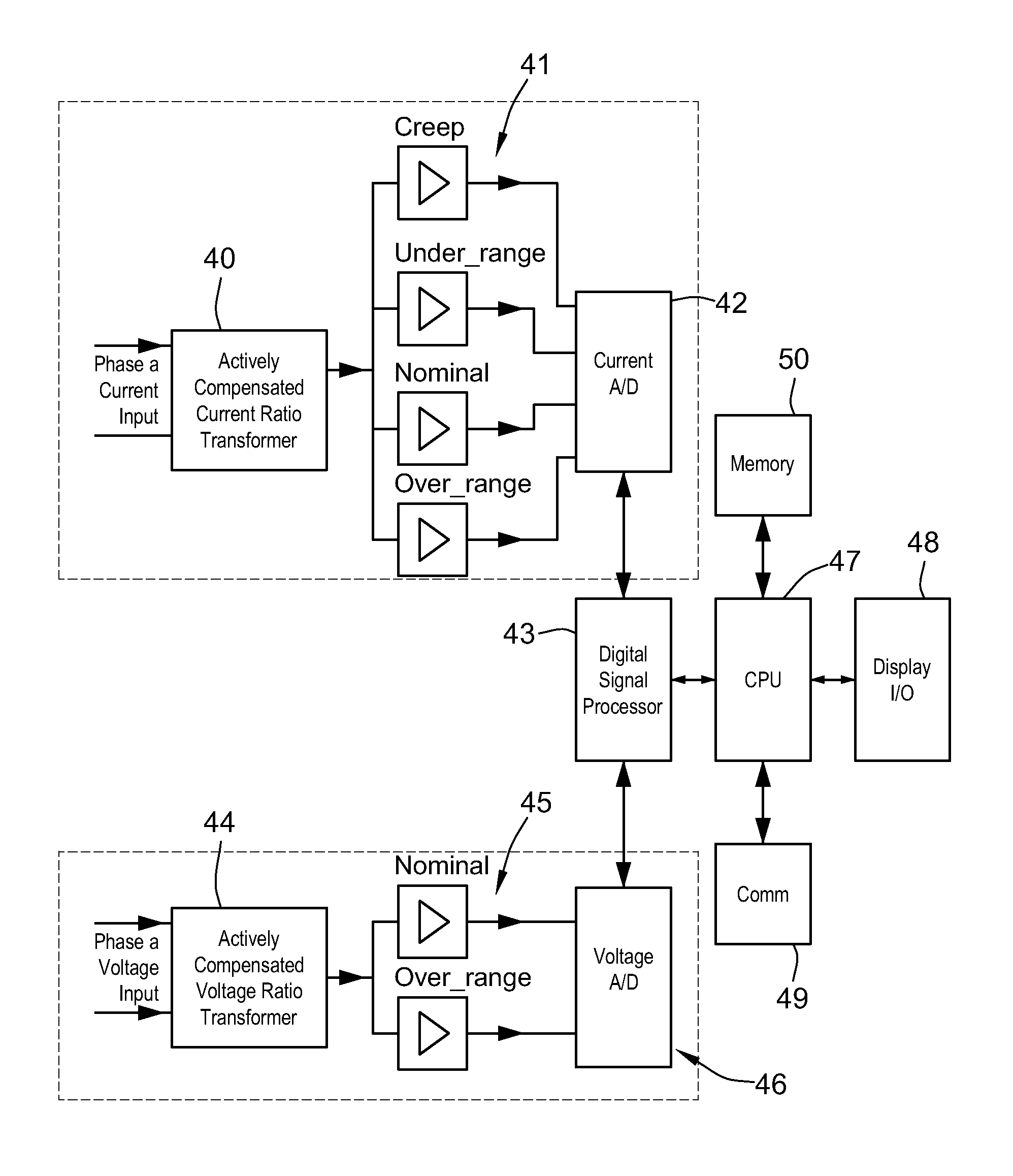
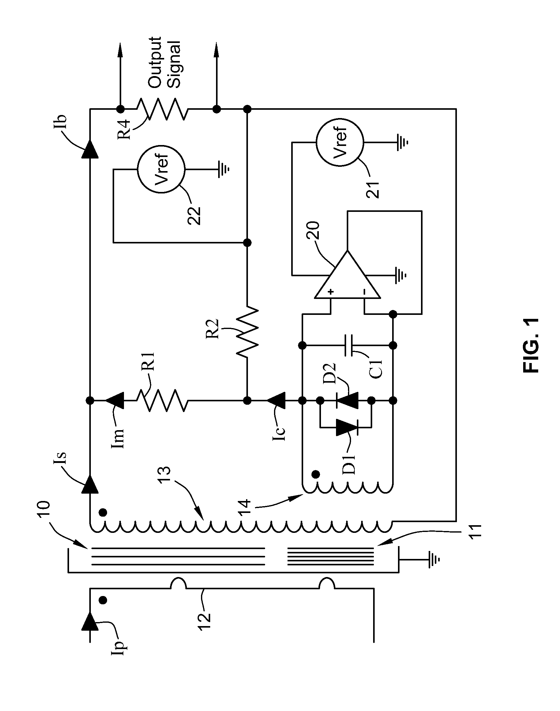
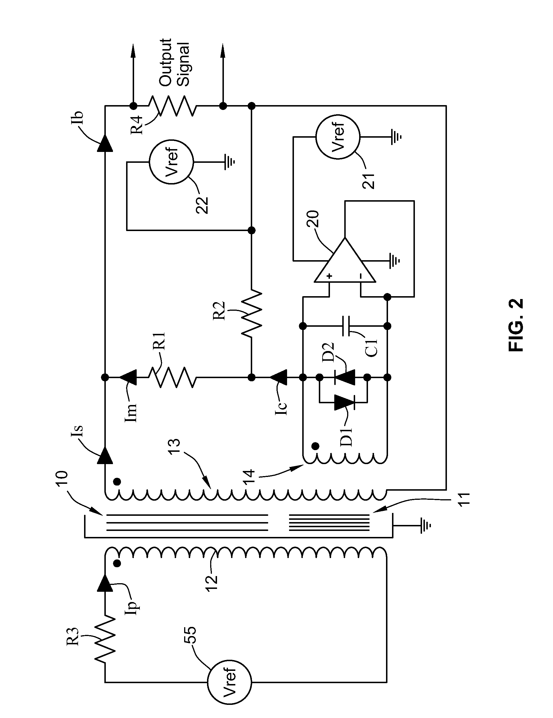
[0015]FIG. 1 shows an actively compensated current ratio transformer device having a lower permeability first “main” core 10, and a higher permeability second “sense” core 11 physically positioned in a stacked arrangement as shown in FIG. 3. The main core is made of a lower cost and lower permeability material (such as a ferrite, e.g., Ferroxcube 3E6 Ferrite), while the sense core 11 is made of a higher permeability metal amorphous core material (such as a base metal composition, e.g., Vacuuschmelze Vitroperm). This combination maximizes accuracy and stability while maintaining a low overall c...


PUM


Abstract

A device for sensing electrical current or voltage in an electrical distribution system using an actively compensated current ratio transformer that includes a first magnetic core having a first permeability and a second magnetic core having a second permeability higher than the first permeability. A primary winding having P turns is coupled with the first and second magnetic cores, a measurement winding having M turns is coupled with the first and second magnetic cores so that current in the primary winding induces current in the measurement winding, and a sense winding having S turns is coupled with the second magnetic core. An amplifier coupled to the sense winding receives a voltage developed across the sense winding and produces a compensation current in response to the received voltage. The amplifier has an output coupled to the sense winding to feed the compensation current through the sense winding to reduce the voltage developed across the sense winding voltage to substantially zero. A burden resistor is coupled to the measurement winding and the sense winding for receiving the sum of the current induced in the measurement winding and the compensation current.

Description

FIELD OF THE INVENTION[0001]This invention relates to precision, alternating current and voltage ratio transformation having primary utility in the accurate measurement of higher current or voltage signals applicable to the field of digital power measurement apparatus having fundamental application in 50-60 Hertz AC power systems.BACKGROUND[0002]Traditional digital power meters typically employ conventional passive internal current transformers and resistive potential dividers in order to reduce relatively large input currents and voltages by a defined and calibrated ratio down to lower currents and voltages that are readily sampled and converted into a digital representation for further signal processing. Current transformers and resistive potential dividers additionally provide much needed electrical isolation between the external current and voltage signals being measured. With potential dividers, the isolation is afforded by providing a robust (transient overload) and high divid...

Claims


Application Information

Patent Timeline
Patent Type & Authority Patents(United States)
IPC IPC(8): G01R15/18G01R11/32
CPCG01R15/183G01R15/185
Inventor GUNN, COLIN N.
Owner SCHNEIDER ELECTRIC USA INC
Why Eureka
Try Eureka