Asymmetrical resistant hinge set

a technology of hinge set and hinge hinge, applied in the direction of wing accessories, instruments, manufacturing tools, etc., can solve the problems of user's arm fatigue, greater gravitational force, and prone to drifting support angle, so as to reduce the resistance of the hinge, reduce the resistance, and reduce the resistance

Inactive Publication Date: 2013-04-23
E LEAD ELECTRONICS
View PDF11 Cites 68 Cited by
  • Summary
  • Abstract
  • Description
  • Claims
  • Application Information

AI Technical Summary

Benefits of technology

[0007]In view of the aforesaid problems, the present invention aims to provide an asymmetrical resistant hinge set that can maintain an anchored position without drifting. To achieve the foregoing object the hinge set according to the invention includes at least a resistant hinge and an elastic element coaxially positioned. The resistant hinge is hinged on a first pivotal means located on the bottom side of a body. The elastic element provides action forces and one-way resistance on the resistant hinge to generate an asymmetrical hinge effect with a greater resistance in one direction and a smaller resistance in another direction when a support lid is flipped in a forward and reverse directions to reduce the resistance of the resistant hinge. As a result, when the support lid is flipped to a selected angle it still can bear the weight of the body of a portable electronic device at the anchored position without drifting.

Problems solved by technology

It's troublesome and easily causes fatigue on user's arm when used in a prolonged duration.
As the electronic device braced by the support rack, after coupling with the screen and circuitry, becomes heavier and is subject to a greater gravitational force, especially when the inclined angle is smaller approaching to the horizontal position.
But the spring 234 of the hinge set 23 does not have an adequate elastic force to bear the load, hence the support angle tends to drift.

Method used


Image

  • Asymmetrical resistant hinge set
  • Asymmetrical resistant hinge set
  • Asymmetrical resistant hinge set

Examples


Embodiment Construction

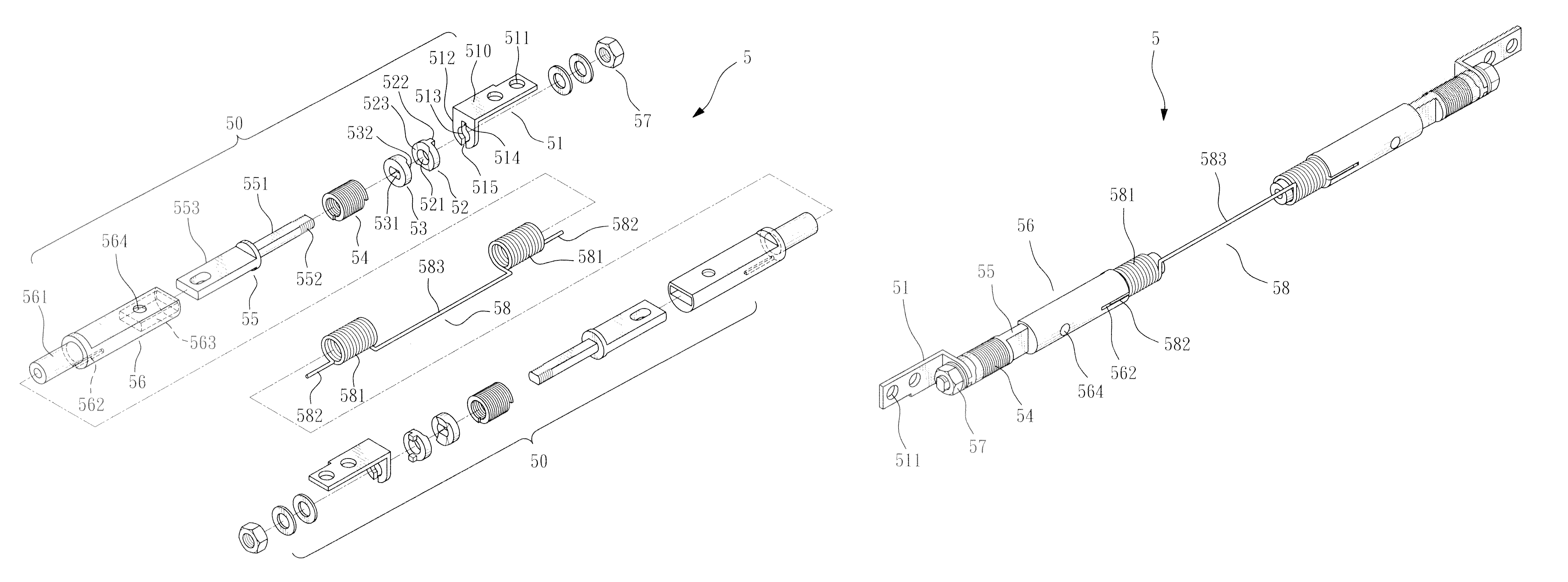
[0022]Please referring to FIGS. 4 through 7, the present invention aims to provide a hinge set 5 which comprises at least a resistant hinge 50 and an elastic element 58 positioned coaxially. The resistant hinge 50 is hinged on a first pivotal means 33 located on the bottom side of a body 3 and a second pivotal means 41 located on the bottom side of a support lid 4. The elastic element 58 provides action forces and one-way resistance on the resistant hinge 50 such that a greater resistance is generated in one direction and a smaller resistance is generated in another direction when the support lid 4 is flipped in a forward direction and reverse direction so that an asymmetrical hinge effect is produced.

[0023]The body 3 consists of an upper half portion 31 and a lower half portion 32 that are coupled together to hold and encase the chassis of an electronic device (such a structure is known in the art, thus details are omitted herein). The upper half portion 31 includes a frame 311 and...


PUM


Abstract

An asymmetrical resistant hinge set includes at least a resistant hinge and an elastic element coaxially positioned. The resistant hinge is hinged on a first pivotal means located on the bottom side of a body. The elastic element provides action forces on the resistant hinge and one-way resistance to generate an asymmetrical hinge effect with a greater resistance in one direction and a smaller resistance in another direction when a support lid is flipped in forward and reverse directions to reduce the resistance of the resistant hinge. As a result, when the support lid is flipped to a selected angle it still can bear the weight of the body of a portable electronic device at the anchored position without drifting.

Description

BACKGROUND OF THE INVENTION[0001]1. Field of the Invention[0002]The present invention relates to an asymmetrical resistant hinge set and particularly to an asymmetrical hinge set adopted for use on a support rack of portable electronic devices to anchor on a selected flipping angle without drifting.[0003]2. Description of the Prior Art[0004]Progress of computers has evolved from housed in a machine room to personal and notebook computers, and now to become touch control portable electronic device 1 (referring to FIG. 1) such as smart phones, tablet computers or the like. Users can directly and intuitively tap a computer screen 10 to select desired items, and splay or narrow two or more fingers to zoom graphics or texts on the screen larger or smaller. Such an operation approach shortens the distance between a user and screen 10 and is much user-friendly than the conventional computer which is operated through a keyboard interposed between the user and screen. The portable electronic...

Claims


Application Information

Patent Timeline
Patent Type & Authority Patents(United States)
IPC IPC(8): E05F1/08
CPCE05D11/084G06F1/1626G06F1/1681G06F2200/1634E05Y2900/606E05Y2800/00Y10T16/5389Y10T16/53828Y10T16/53826Y10T16/5381Y10T16/5382Y10T16/5398Y10T16/53845
Inventor CHEN, STEPHEN
Owner E LEAD ELECTRONICS
Why Eureka
Try Eureka