Charging device for electric vehicle

a charging device and electric vehicle technology, applied in hybrid vehicles, vehicle sub-unit features, coupling device connections, etc., can solve the problems of large user-friendliness of electric vehicles, achieve simultaneous charging, shorten the total charging time, and improve the charging operability of electric vehicles

Active Publication Date: 2013-04-23
SUBARU CORP
View PDF14 Cites 32 Cited by
  • Summary
  • Abstract
  • Description
  • Claims
  • Application Information

AI Technical Summary

Benefits of technology

[0013]In the charging device for an electric vehicle according to the present invention, when the external power source is connected to the first connection terminal and the external charger is connected to the second connection terminal, the charging system switching means activate the charging circuit having a shorter total charging time, from among the first charging circuit and the second charging circuit, such that the charging device is charged through the charging circuit having the shorter total charging time.
[0015]According to the present invention, the charging system switching means charge the storage device from only one of the first and second charging circuits and prevent simultaneous charging from both circuits. Therefore, even when the electric vehicle is provided with both a fast charging connection terminal to which a power supply plug of a fast charger is connected and a normal charging connection terminal to which an external power source for supplying electric power to an on-board charger is connected, the storage device is invariably charged via a single charging circuit. Hence, simultaneous fast charging and normal charging can be prevented and optimum charging can be performed, enabling an improvement in the charging operability of the electric vehicle.
[0016]When the fast charging connection terminal and the normal charging connection terminal are provided separately in the vehicle body and both the power source plug and the power supply plug are connected to the respective connection terminals, simultaneous charging through both of the charging circuits is prevented by prioritizing either the charging circuit having the connection terminal that was connected first or the charging circuit having the shorter total charging time. When the vehicle body is provided with an aggregate connection terminal in which the fast charging connection terminal and the normal charging connection terminal are provided collectively, simultaneous charging through both of the charging circuits is prevented by ensuring that only one of the power source plug and the power supply plug can be connected to the aggregate connection terminal at a time.

Problems solved by technology

However, several hours are required to charge the storage device to a high voltage of up to approximately DC 400V, for example, by connecting a power source plug, or in other words an outlet, of an AC 100V or AC 200V household commercial power source to the vehicle body, and since this amount of time is excessive, an electric vehicle suffers greatly in terms of user-friendliness in comparison with a gasoline vehicle having a fuel tank that can be filled in a short period of time at a gas station.
Nevertheless, when both the high-speed charging connector and the normal charging connector are provided on the vehicle body, a user may mistakenly connect the power supply plug of the high-speed charger and the normal charging power source plug at the same time.

Method used


Image

  • Charging device for electric vehicle
  • Charging device for electric vehicle
  • Charging device for electric vehicle

Examples


Embodiment Construction

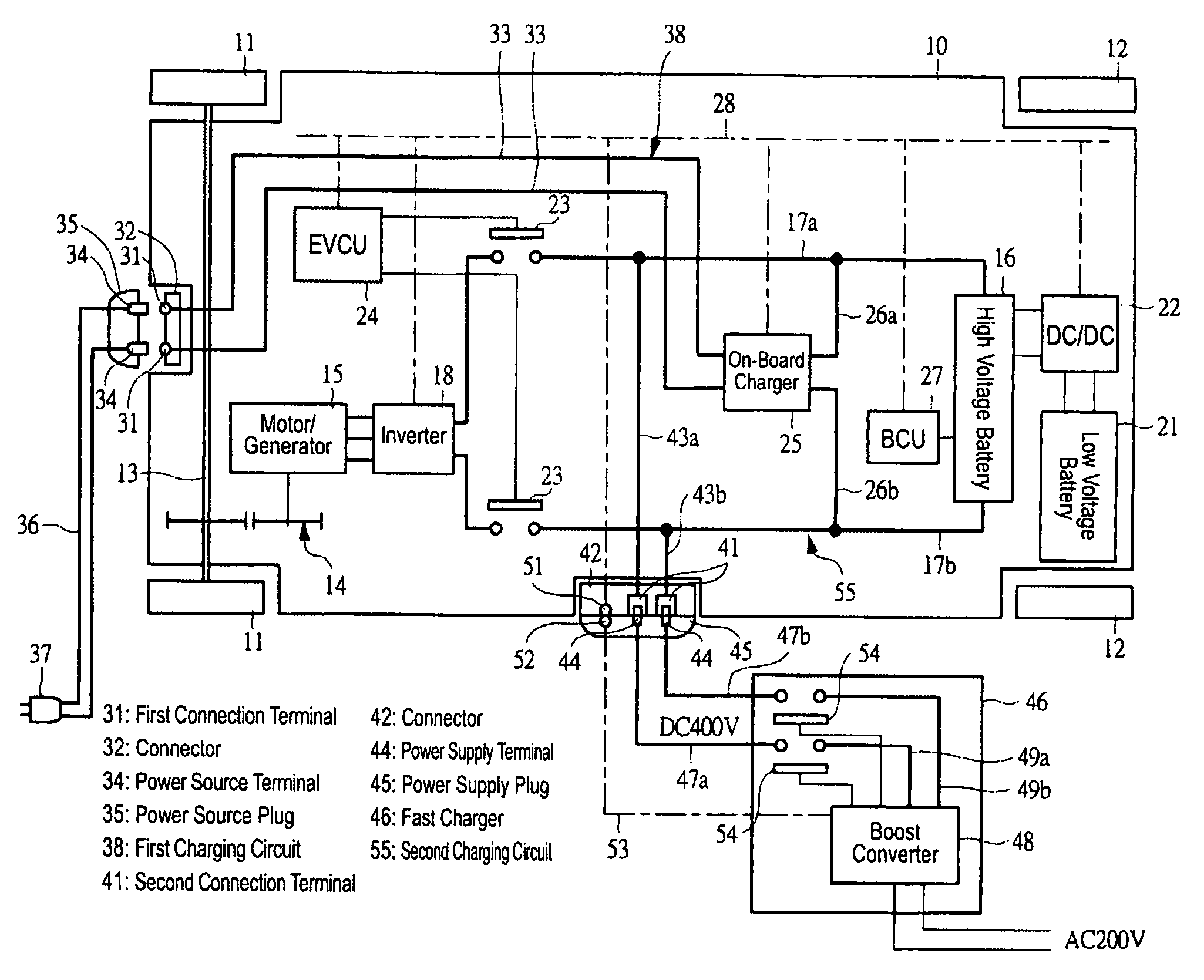
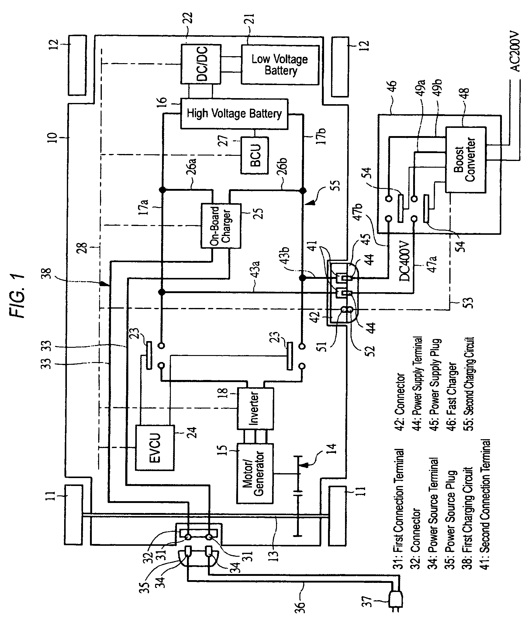
[0024]Embodiments of the present invention will be described in detail below on the basis of the drawings. FIG. 1 is a schematic diagram showing an electric vehicle having a charging device serving as an embodiment of the present invention.

[0025]A vehicle body 10 of this electric vehicle is provided with drive wheel side front wheels 11 and driven wheel side rear wheels 12, and a motor / generator 15 is connected to a drive shaft 13 for driving the front wheels 11 via a pair of gears 14 having a fixed gear ratio. The motor / generator 15, which serves as an electric motor for driving the vehicle, is a three-phase alternating current synchronous motor, and a high voltage battery 16 for supplying electric power to the motor / generator 15 is installed in the vehicle body 10 as a storage device. The high voltage battery 16 employs a lithium ion battery, i.e. a secondary battery, and outputs direct current power of 400V, for example.

[0026]The high voltage battery 16 is connected to an inverte...


PUM


Abstract

The present invention provides a charging device for an electric vehicle with which optimal charging can be performed reliably when charging a storage device of the electric vehicle, without performing fast charging and normal charging at the same time.

Description

CROSS-REFERENCE TO RELATED APPLICATIONS[0001]The disclosure of Japanese Patent Application No. 2007-244748, filed on Sep. 21, 2007 including the specification, drawings and abstract is incorporated herein by reference in its entirety.BACKGROUND OF THE INVENTION[0002]1. Field of the Invention[0003]The present invention relates to a charging device for an electric vehicle, which charges a storage device that supplies electric power to an electric motor for driving a vehicle.[0004]2. Description of the Related Art[0005]Electric vehicles include vehicles that use an electric motor alone as a drive source and hybrid vehicles that uses an electric motor and an engine as drive sources. Both types of electric vehicle include a battery serving as a storage device for supplying electric power to the electric motor, and when the remaining capacity of the battery decreases, the battery must be charged externally. Further, in a hybrid vehicle that uses both an electric motor and an engine as dri...

Claims


Application Information

Patent Timeline
Patent Type & Authority Patents(United States)
IPC IPC(8): H02J7/00
CPCB60K6/28B60L11/14B60L11/1811B60L11/1818B60L11/1824B60L11/1838B60L11/185B60W10/26B60K6/48Y02T10/70B60L2210/20B60W20/00Y02T10/6221Y02T10/6269Y02T10/6278Y02T10/7005Y02T10/7077Y02T10/725Y02T90/121Y02T90/127Y02T90/128Y02T90/14B60Y2400/112B60L50/16B60L53/11B60L53/16B60L53/20B60L53/66Y02T10/62Y02T10/7072Y02T10/72Y02T90/12Y02T90/16B60W20/13B60W2510/244B60W2710/244
Inventor OHTOMO, YOSUKE
Owner SUBARU CORP
Why Eureka
Try Eureka