Smartcard and method for the production of a smartcard

Active Publication Date: 2013-04-23
LINXENS HLDG SAS
View PDF21 Cites 1 Cited by
  • Summary
  • Abstract
  • Description
  • Claims
  • Application Information

AI Technical Summary

Benefits of technology

[0015]Similarly, a winding separation distance of a fourth conducting lead may differ from those of the first, second and third conducting leads. The design of conducting leads having differing winding separation distances opens up the possibility of a wide range of geometric combinations in terms of matching the antenna and the chip.
[0016]In further advantageous embodiments of the smartcard, a conductor of the antenna may be routed over the conductor connection surfaces of the chip to serve as a compensation loop, wherein a remaining wire end is not contacted, thus remains free and has a capacitive effect on the antenna coil. This in turn offers an additional option for adapting the antenna, wherein the electrical properties may be influenced by the distance of the winding from the adjacent conductor and by the length of the remaining free wire end. The antenna may also be matched by laying a conductor in a meandering pattern.
[0017]In the method according to the invention for producing a smartcard, a resulting resonance frequency of the transponder unit, which is modified depending on the capacitance and impedance of a chip, is designed to match a frequency emitted by a reader unit in such manner that the outputs of the antenna and the chip are matching. The matching between antenna and chip is achieved by changing the geometry of the antenna, the change taking the form of placing the antenna on a substrate in such manner that least one conducting lead is arranged asymmetrically with respect to at least a second conducting lead extending parallel thereto, with the result that the winding separation distance of the first conducting lead differs from the winding separation distance of the second conducting lead.

Problems solved by technology

The impedances in the chip and the antenna may be matched using discrete components, but this is undesirable in smartcards of the type described above because of the associated high production costs.

Method used


Image

  • Smartcard and method for the production of a smartcard
  • Smartcard and method for the production of a smartcard
  • Smartcard and method for the production of a smartcard

Examples


Embodiment Construction

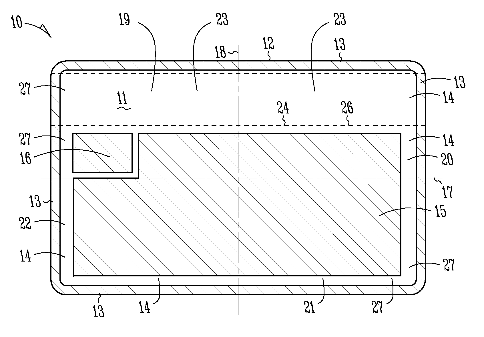
[0024]FIG. 1 shows a smartcard 10 with a card surface 11 within a card contour 12. Along card contour 12, card 10 has an edge area 13 that surrounds a patch 14. In turn, patch 14 encloses an embossing surface 15, within which embossing—not shown here—may be applied, and a chip surface 16, within which a chip—not shown here—may be placed. The areas defined by embossing surface 15 and chip surface 16 are arranged inside patch 14 such that communicating patch zones 19, 20, 21 and 22 are formed in patch 14. The antenna geometries shown in FIG. 2 and FIG. 3 may be formed inside these patch zones 19, 20, 21 and 22, whereas embossing surface 15, chip surface 16 and edge area 13 are not intended for the formation of such an antenna.

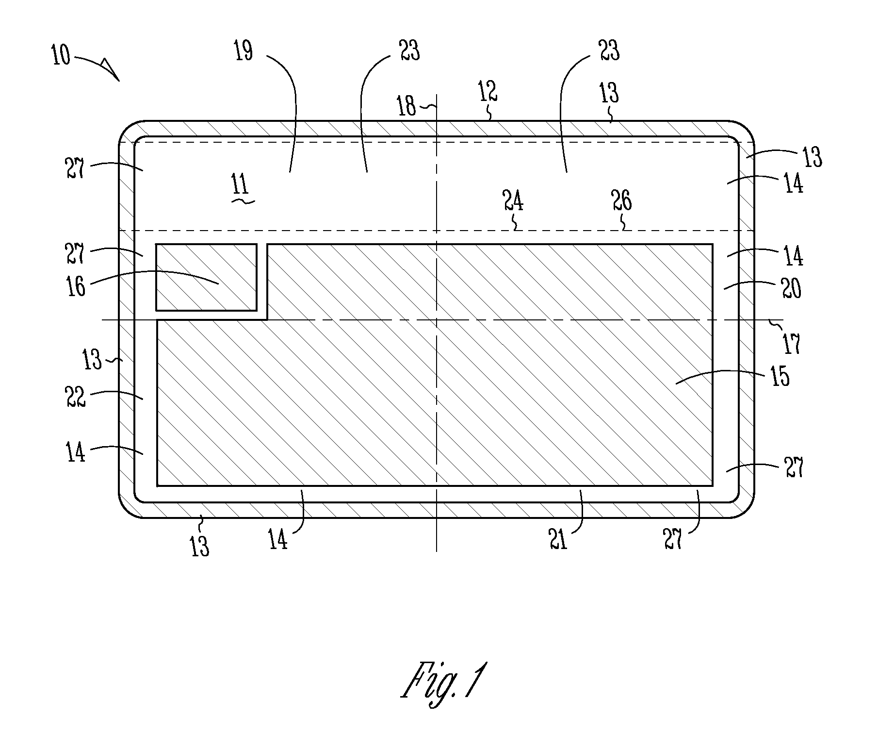
[0025]Patch zones 19, 20, 21 and 22 are arranged essentially parallel to the axes of symmetry 17 and 18 of smartcard 10, wherein particularly patch zone 19 is relatively large compared to patch zones 20, 21 and 22. A magnetic strip 24 is arranged on a patch 23 th...


PUM


Abstract

The invention relates to a smartcard, particularly an electronic prepayment card, identification card or similar, with at least one transponder unit, and to a method for producing such a smartcard, wherein the transponder unit has at least one chip and at least one antenna connected to the chip, wherein the antenna is made from a conductor that is arranged on an antenna substrate, wherein the extension of the antenna is limited to a patch of the antenna substrate and the antenna has a plurality of conducting lead with at least two windings separated from each other, which windings are arranged so that their axes are at least partly parallel to an axis of symmetry of the smartcard.

Description

RELATED APPLICATIONS[0001]This application is a nationalization under 35 U.S.C. 371 of PCT / EP2007 / 004661, filed on May 25, 2007, and published as WO 2008 / 000325 A1 on Jan. 3, 2008, which claimed priority under 35 U.S.C. 119 to German Patent Application Serial No. 10 2006 030 819.0, filed Jun. 30, 2006; which applications and publication are incorporated herein by reference and made a part hereof.TECHNICAL FIELD[0002]The technical field of the invention relates to smartcards with inductively coupled transponders, such as are used in so-called “RFID systems”.BACKGROUND OF THE INVENTION[0003]Passive, inductively coupled transponder units essentially include a chip as a data carrier and a large-area coil that functions as an antenna. When used in a smartcard, electronic prepayment card or similar, the transponder unit is enclosed between various laminate layers of the card and can be read out without contact by a transmitting or reader unit or directly using external contact areas on th...

Claims


Application Information

Patent Timeline
Patent Type & Authority Patents(United States)
IPC IPC(8): G08B13/14
CPCG06K19/0726G06K19/07749G06K19/07779G06K19/07781G06K19/07783H01Q1/2225H01Q9/27
Inventor RIETZLER, MANFREDCASTANO, PHILIPPE
Owner LINXENS HLDG SAS
Why Eureka
Try Eureka