
Daisy chaining device servers via ethernet

a technology of ethernet and ethernet connections, applied in the field of serial communications over ethernet, can solve the problems of limiting the ability of proprietary vendors to incorporate new networking innovations, and affecting the performance of the network

Active Publication Date: 2013-04-23
LANTRONIX
View PDF23 Cites 6 Cited by
  • Summary
  • Abstract
  • Description
  • Claims
  • Application Information

AI Technical Summary

Benefits of technology

The present invention provides a device server that facilitates connecting other devices in a daisy chain manner. The device server includes an Ethernet switch, first and second Ethernet connections, and a serial communications port. The device server can be powered by both AC and DC power, and can be mounted on a supporting structure. The device server has Ethernet switch functions and can include a serial to Ethernet converter for connecting serial ports. The technical effects of the invention are improved convenience, reliability, and flexibility in device-to-device connections.

Problems solved by technology

But practical difficulties still remain.
This has many advantages well understood in the networking field, but in some fields of use, especially industrial and building automation, this “star” topology is not optimal.
While this series topology is beneficial in minimizing wiring and installation expense in these fields, the lack of a strong unifying standard such as Ethernet has fragmented these markets with various proprietary hardware and software offerings, and customers have as a result become locked into a particular manufacturer's offerings, limiting their ability to incorporate new networking innovations to what their proprietary vendor can implement and support.
Additionally, as a practical limitation, the equipment, tools and techniques required to fabricate and install the types of power supply and communications connectors used in traditional IT networks differ significantly from common practice and skills found in, for example, the construction industry.
This mismatch makes the physical installation and maintenance of the network more difficult.
Furthermore, where a definition or use of a term in a reference, which is incorporated by reference herein is inconsistent or contrary to the definition of that term provided herein, the definition of that term provided herein applies and the definition of that term in the reference does not apply.

Method used


Image

  • Daisy chaining device servers via ethernet
  • Daisy chaining device servers via ethernet
  • Daisy chaining device servers via ethernet

Examples


Embodiment Construction

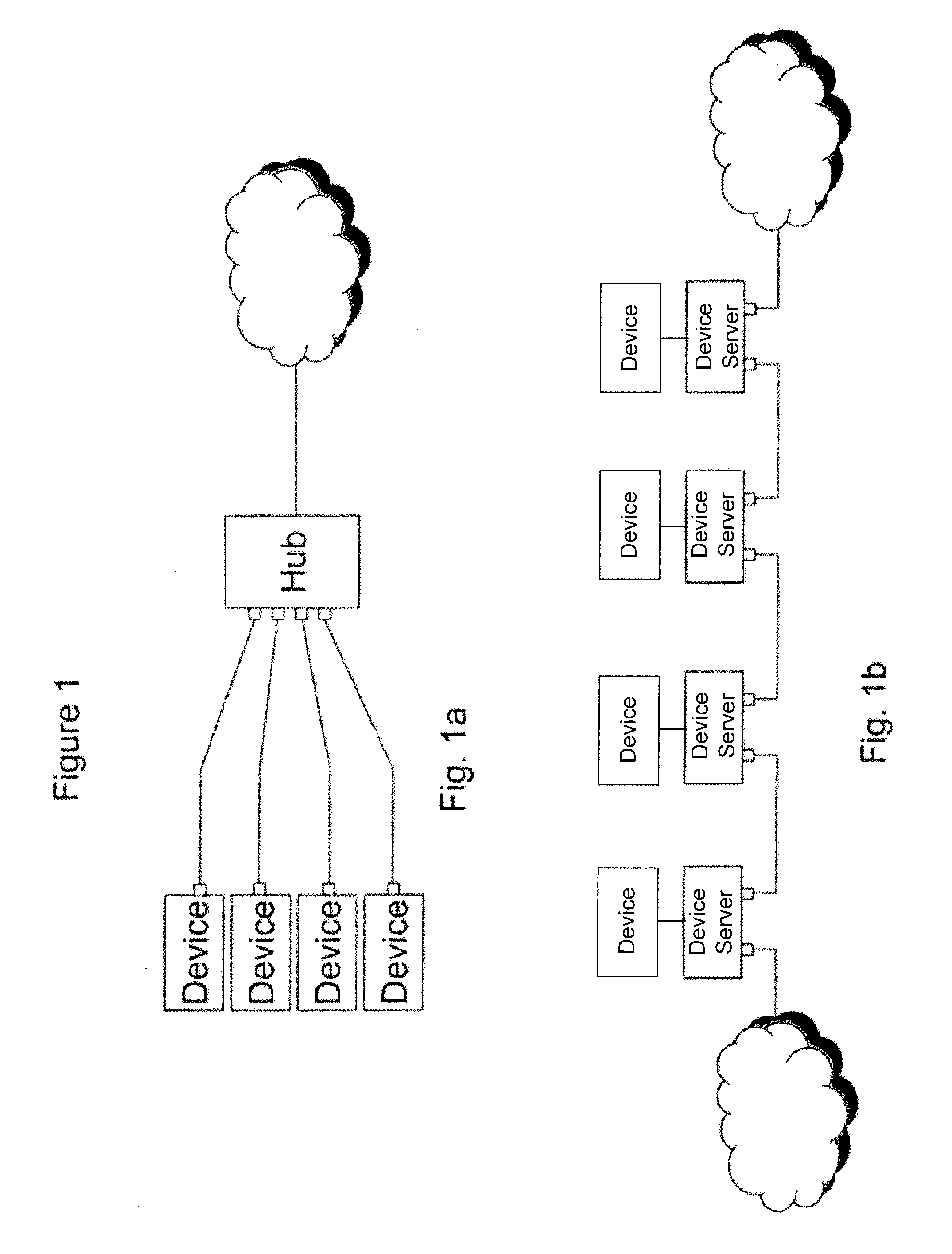
[0021]FIG. 1 compares two topologies. FIG. 1a shows an Ethernet “star” topology, while FIG. 1b shows a “daisy chain” topology wherein devices are connected in series, one after the other in linear fashion, by using two Ethernet ports on each daisy chained device.

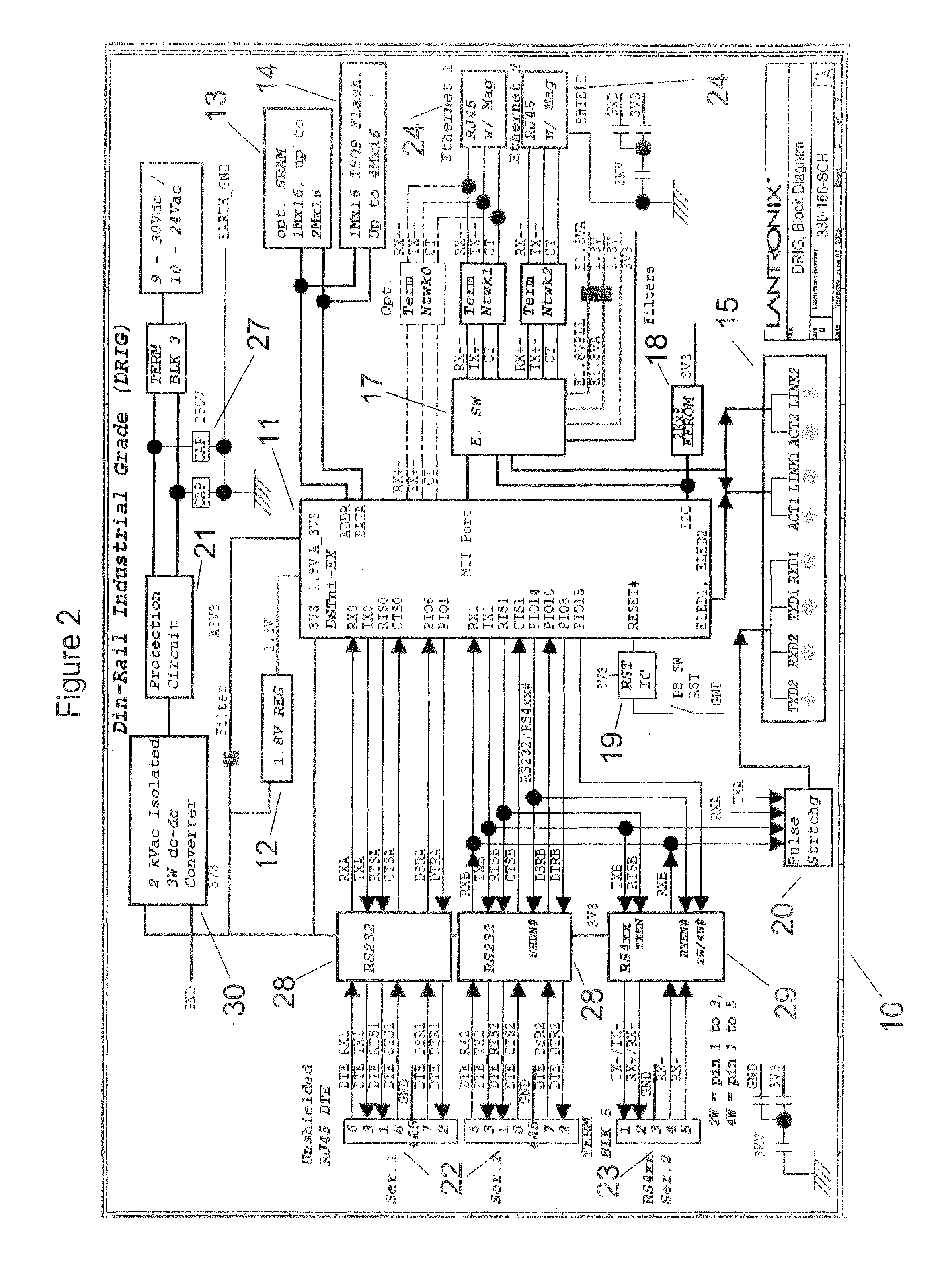
[0022]Referring to FIG. 2, in a preferred embodiment the device server circuit board 10 interconnects the device server circuitry. The control microprocessor 11 is DSTni-EX, a System-on-chip (SOC) integrated circuit. DSTni-EX includes serial communications ports, on-board RAM and ROM, an Ethernet MAC and PHY, and ample address and data lines to connect and control lights and GPIO pins. A DC to DC converter 30, capable of supplying a 3 Watt load is galvanically isolated from input to output by a breakdown rating of 2000 volts. A protection circuit 21 prevents electrical overstress of the converter by absorbing and dissipating excess joules of energy. The protection circuit also accepts AC and DC input and with diode steering ...


PUM


Abstract

A device server intended for attaching serial devices to a network includes Ethernet communications, an Ethernet switch, and serial communication capability so that multiple device servers are connected in a “daisy chain” or series pattern. Galvanic isolation of the power supply from the housing and communication ports, screw terminal and modular connections, DIN rail mounting, broad power supply voltage ranges or “Power-over-Ethernet” and operator visible indicator lamps with a pulse stretching feature greatly simplify installation and use.

Description

FIELD OF THE INVENTION[0001]The field of the invention is serial communications over Ethernet.BACKGROUND[0002]There is a long history of remote communication and control of instruments, especially instruments and devices with a serial interface. Initially control elements were interfaced to devices using direct serial connections, but with the ubiquity of networks and the world wide web, remote control via web browsers became feasible (See as examples U.S. Pat. Nos. 6,139,177 and 6,373,841). Devices designed with native web interfaces could connect directly to a computer network. And to accommodate the vast base of legacy devices without built in network connections, adapters were developed that connected a serial device to a network. These Serial to Ethernet converters, also referred to as “device servers”, have been developed to an advanced degree, both in software, where innumerable pre-programmed, customizable and programmable features are supported, and in hardware, where the e...

Claims


Application Information

Patent Timeline
Patent Type & Authority Patents(United States)
IPC IPC(8): H04L12/50H04Q11/00
CPCH04L12/10H04L12/40006H04L49/602
Inventor MILLER, DARYL R.
Owner LANTRONIX
Learn More