
Low insertion force electrical connector for implantable medical devices

a technology of low insertion force and electrical connector, which is applied in the direction of coupling contact member, coupling device connection, therapy, etc., can solve the problems of large removal of surgical components and attendant risk factors, and the complex pulse generator of some applications, and achieve the effect of widening the toleran

Active Publication Date: 2013-04-23
CIRTEC MEDICAL CORP
View PDF86 Cites 38 Cited by
  • Summary
  • Abstract
  • Description
  • Claims
  • Application Information

AI Technical Summary

Benefits of technology

The present electrical connector allows for the coil contacts to move in multiple directions without affecting the coil spring. This enables wider tolerances between the electrical contact and the therapy delivery element or extension. The coil springs can also compress radially when an outward force is applied, providing an additional degree of freedom. This is different from previous designs where the springs could only move in one direction.

Problems solved by technology

Once the leads are implanted in the body, removal may involve major surgery with attendant risk factors.
While some pulse generators only require a few leads, pulse generators for some applications are very complex and require a large number of discrete electrical impulses each delivered by a discrete lead.

Method used


Image

  • Low insertion force electrical connector for implantable medical devices
  • Low insertion force electrical connector for implantable medical devices
  • Low insertion force electrical connector for implantable medical devices

Examples


Embodiment Construction

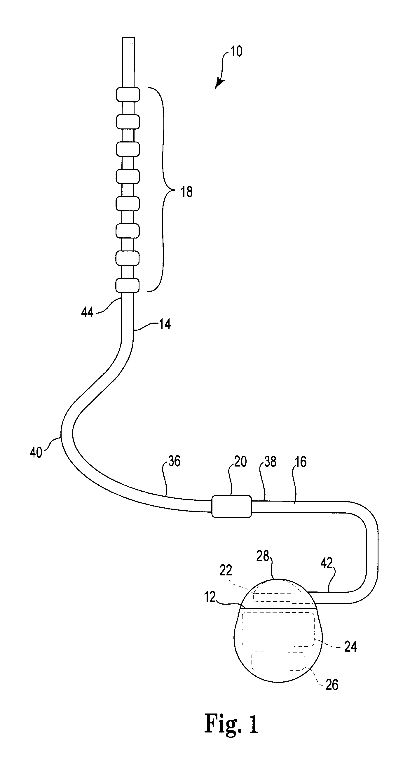
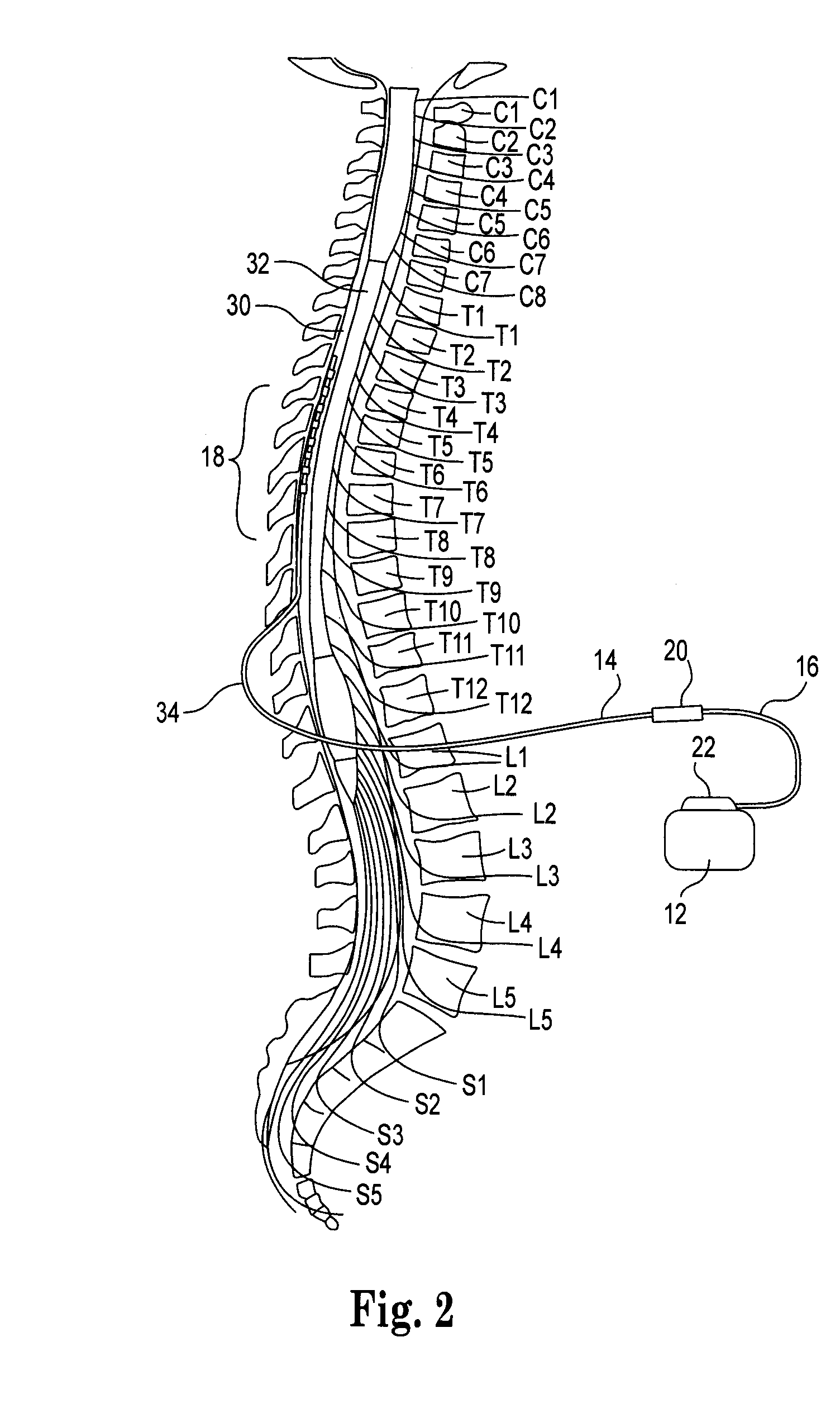
[0041]The description that follows relates to a spinal cord stimulation (SCS) system. However, it is to be understood that the while the present disclosure lends itself well to applications in SCS, the disclosure in its broadest aspects may not be so limited. Rather, the disclosure may be used with any type of implantable therapy delivery system with one or more therapy delivery elements. For example, the present disclosure may be used as part of a pacemaker, a defibrillator, a cochlear stimulator, a retinal stimulator, a stimulator configured to produce coordinated limb movement, a cortical stimulator, a deep brain stimulator, peripheral nerve stimulator, microstimulator, or in any other neural stimulator configured to treat urinary incontinence, sleep apnea, shoulder sublaxation, headache, etc.

[0042]In another embodiment, one or more of the therapy delivery elements may be a fluid delivery conduit, such as a catheter, including an inner lumen that is placed to deliver a fluid, suc...


PUM

PropertyMeasurementUnit
lengthaaaaaaaaaa
lengthaaaaaaaaaa
rotationaaaaaaaaaa

Abstract

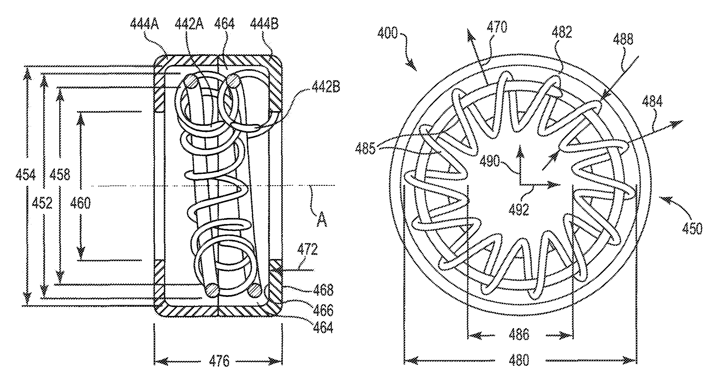
A low-insertion force electrical connector for implantable medical devices. The electrical contact includes a housing with a pair of opposing sidewalls each with center openings oriented generally concentrically around a center axis. The housing also includes a recess with a recess diameter. An inner coil is located in the recess with a coil axis generally co-linear with the center axis of the center openings. The inner coil includes an outer diameter less than the recess diameter, and an inner diameter greater than a center opening diameter. An outer coil is threaded onto the inner coil to form a generally toroidal-shape. The outer coil has an outer diameter less than the recess diameter, and an inner diameter less than the center opening diameter. The outer coil is radially expanded within the recess in response to engagement with contact rings on the implantable medical device, such that the outer diameter of the outer coil is at least equal to the recess diameter.

Description

FIELD[0001]The present disclosure is directed to a low-insertion force electrical connector for implantable medical devices, and to a connector assembly including a plurality of the low-insertion force electrical contacts.BACKGROUND[0002]Implantable medical electronics devices consist of an implanted pulse generator that is used to provide electrical stimulation to certain tissues and an implantable lead or leads that are used to transmit the electrical impulse to the targeted tissues. Examples include cardiac pacemaking, and a number of related applications for cardiac rhythm management, treatments for congestive heart failure, and implanted defibrillators. Other applications for implantable pulse generators include neurostimulation with a wide range of uses such as pain control, nervous tremor mitigation, incontinent treatment, epilepsy seizure reduction, vagus nerve stimulation for clinical depression, and the like. This rapidly growing field will undoubtedly have even wider appl...

Claims


Application Information

Patent Timeline
Patent Type & Authority Patents(United States)
IPC IPC(8): A61N1/375
CPCA61N1/3752H01R13/187H01R13/33A61N1/3605A61N1/0551H01R24/58H01R2107/00H01R2201/12Y10T29/49117A61N1/36125Y10S439/909
Inventor SAGE, SHAHN S.
Owner CIRTEC MEDICAL CORP
Learn More