Saw tooth for circular saw

a circular saw and saw tooth technology, applied in the direction of metal sawing devices, sawing devices, sawing apparatuses, etc., can solve the problems of increased fuel consumption, reduced productivity, and relatively quick wear of saw teeth

Active Publication Date: 2013-04-30
2396002 ONTARIO
View PDF42 Cites 10 Cited by
  • Summary
  • Abstract
  • Description
  • Claims
  • Application Information

AI Technical Summary

Problems solved by technology

Saw teeth wear relatively quickly and may become rounded or dull.
This may cause increased fuel consumption, decreased productivity, or poor cut quality, or all of them, and may tend to result in a need for maintenance.
This may tend to result in increased friction and the tearing of tree fibers, instead of cutting the tree fibers with a shearing action.
This may tend to consume more energy, decrease machine productivity and produce a rougher cut on the tree butt.
The outermost cutting tips of the teeth are also susceptible to damage from impact, such as when the teeth strike objects such as rocks and other debris during the felling of trees.
This may also lead to a need for maintenance.
These corners may tend to chip or break off easily when striking objects or debris.
This may result in a loss of the cutting edge and in a loss of cutting efficiency.
These may be more durable but may become rounded or dull faster and may be less efficient at cutting tree fibers.

Method used


Image

  • Saw tooth for circular saw
  • Saw tooth for circular saw
  • Saw tooth for circular saw

Examples


Embodiment Construction

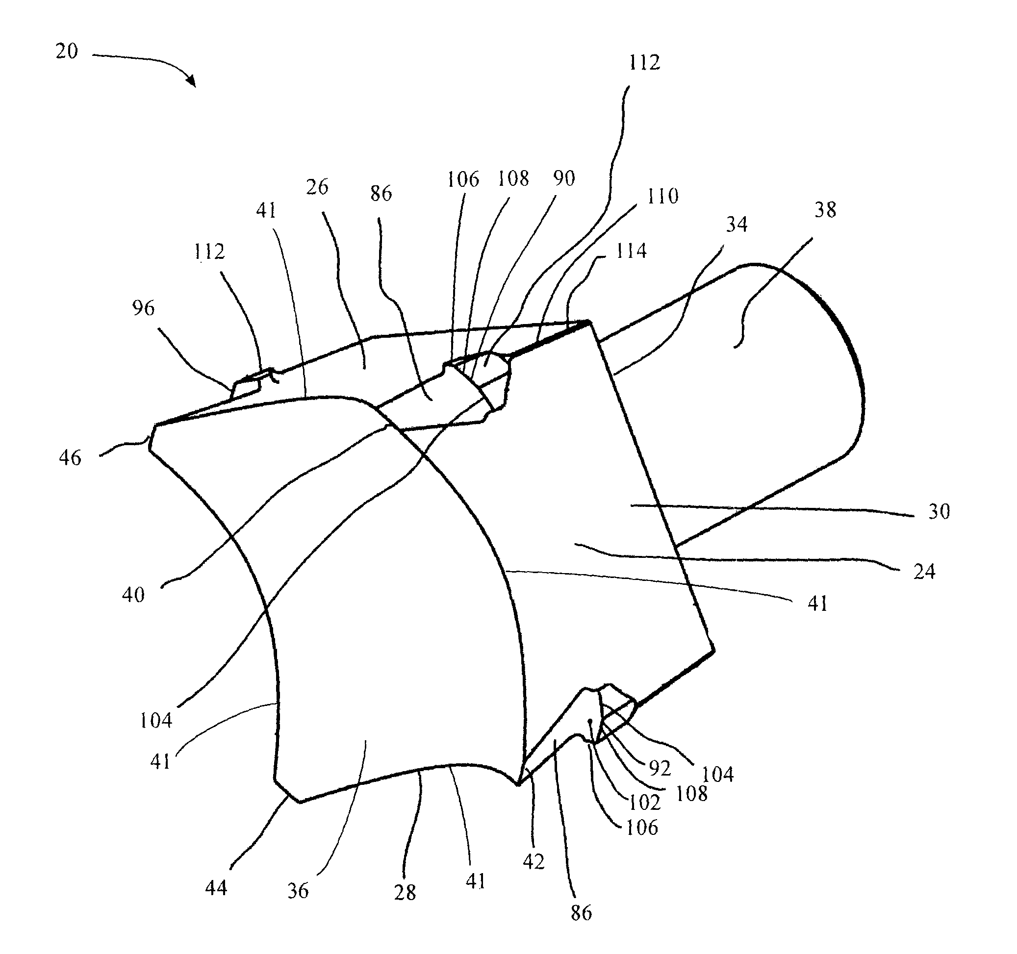
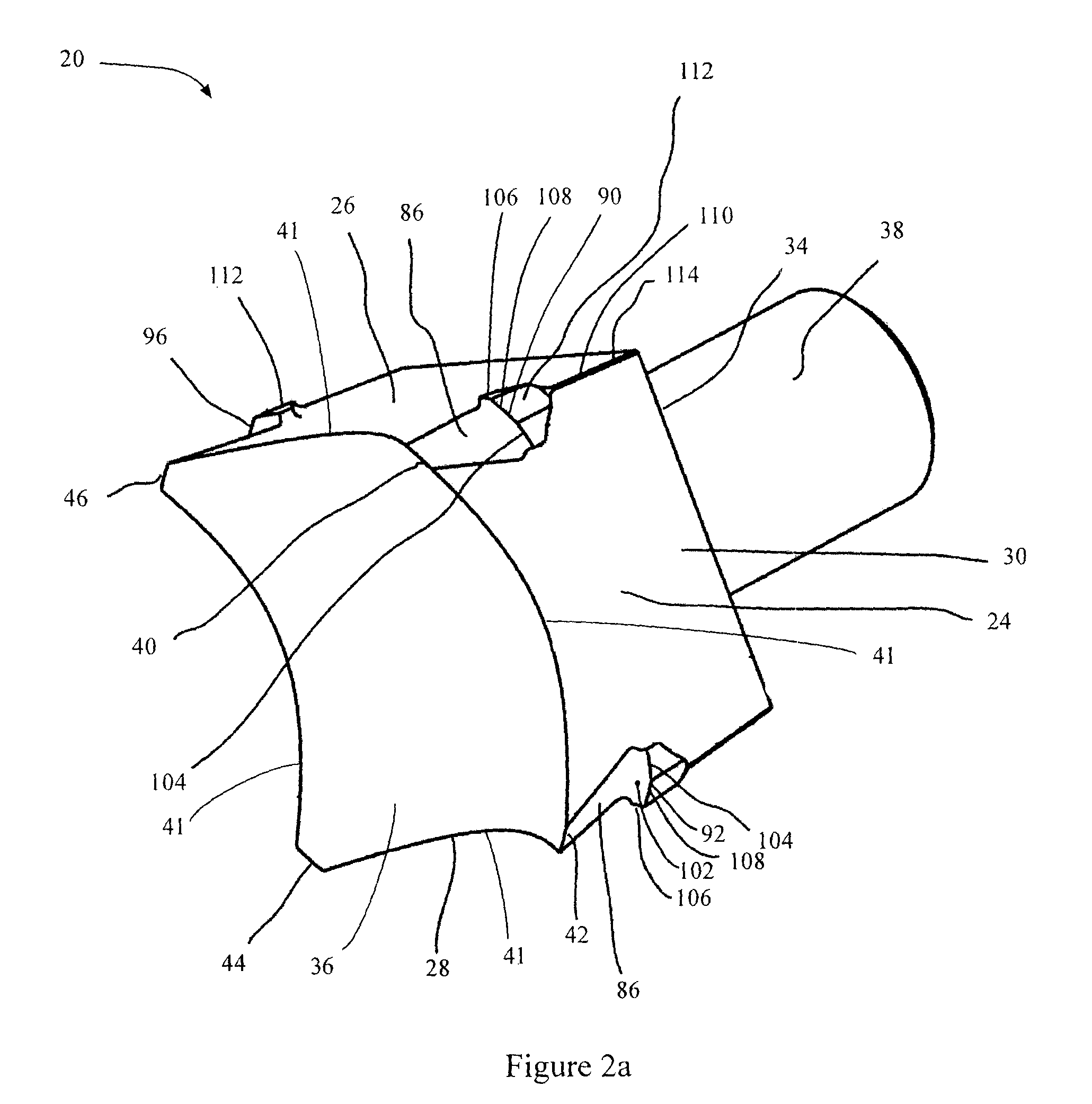
[0037]The description that follows, and the embodiments described therein, are provided by way of illustration of an example, or examples of particular embodiments of the principles of the present invention. These examples are provided for the purposes of explanation, and not of limitation, of those principles and of the invention. In the description, like parts are marked throughout the specification and the drawings with the same respective reference numerals. The drawings are not necessarily to scale and in some instances proportions may have been exaggerated in order more clearly to depict certain features of the invention.

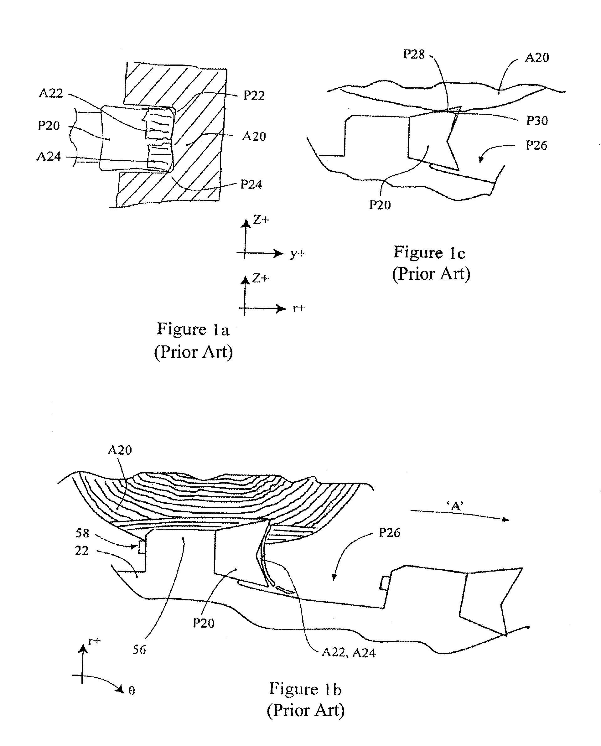
[0038]It may be helpful to identify co-ordinate systems that may aid in understanding the present invention. At the largest level, there may be a cylindrical polar co-ordinate system, in which the axial, or x-direction is defined by the axis of rotation of a feller buncher disc saw blade. The circumferential direction is that through which angles, angular velo...


PUM

PropertyMeasurementUnit
angleaaaaaaaaaa
angleaaaaaaaaaa
angular displacementaaaaaaaaaa

Abstract

A tooth is provided for a circular disc felling saw. When installed on a saw blade, the tooth has both leading and trailing cutting tips that cut the tree. The cutting discharge of the trailing cutting tips may tend to wear the rearward flank of the leading cutting tips. Either one or both of the primary and secondary cutting tips may include a wear insert, such as a ceramic wear insert.

Description

CROSS REFERENCE TO RELATED APPLICATIONS[0001]The present application is a 35 U.S.C. §371 National Phase conversion of PCT / CA2008 / 000066, filed Jan. 11, 2008, which claims benefit of U.S. Provisional Application No. 60 / 897,873, filed Jan. 29, 2007, the disclosure of which is incorporated herein by reference. The PCT International Application was published in the English language.FIELD OF THE INVENTION[0002]The present invention relates to saw teeth for circular saws.BACKGROUND OF THE INVENTION[0003]Saw teeth for circular saws of the type mounted on a feller head for a tree felling apparatus are known. U.S. Pat. No. 4,932,447, Morin, 1990, and U.S. Pat. No. 5,205,199, MacLennan, 1993, represent saw teeth that have become well known in the industry. Morin '447 and MacLennan '199 both teach a replaceable saw tooth with four sides. The teeth can be rotated when the active cutting tips and edges become dull or worn.[0004]Saw teeth wear relatively quickly and may become rounded or dull. Th...

Claims


Application Information

Patent Timeline
Patent Type & Authority Patents(United States)
IPC IPC(8): B27B33/02
CPCB23D61/065B27B33/08Y10T83/935Y10T83/9324Y10T83/9326Y10T83/9329
Inventor MICACCHI, MAURICE
Owner 2396002 ONTARIO
Why Eureka
Try Eureka