Swivel spout assembly

a spout and spout technology, which is applied in the direction of mechanical equipment, transportation and packaging, and functional valve types, etc., can solve the problems of affecting the use of the spout, the spout the middle of the tube will be subjected to strain, so as to avoid any perceived damage, avoid leakage, and avoid corrosion of the metallic housing

Active Publication Date: 2013-04-30
KOHLER CO
View PDF10 Cites 12 Cited by
  • Summary
  • Abstract
  • Description
  • Claims
  • Application Information

AI Technical Summary

Benefits of technology

[0016]Importantly, the combination of the telescoping connection and seal between the connector sleeves avoids leakage, while still permitting relative rotation. Also, means are provided to keep the telescoping parts from axially separating from each other, without introducing undesired resistance to spout swiveling.
[0017]As a polymeric tube structure can carry potable water from the mixing valve to the spout outlet, contact between the potable water and the spout housing is reduced or avoided. This avoids corrosion of the metallic housing, and may avoid any perceived risk of lead or other content of the metal housing leaching into the potable water.

Problems solved by technology

On the other hand, including such a tube in a spout that swivels as desired for use in a kitchen environment is more problematic.
In this regard, if one end of the tube is fixed to a mixing valve, and the other swivels with the spout, the middle of the tube will be subjected to strain.
This can create resistance to the swiveling, a tendency of the spout to remain in a swiveled position, and a potential wear point that may break.

Method used


Image

  • Swivel spout assembly
  • Swivel spout assembly
  • Swivel spout assembly

Examples


Embodiment Construction

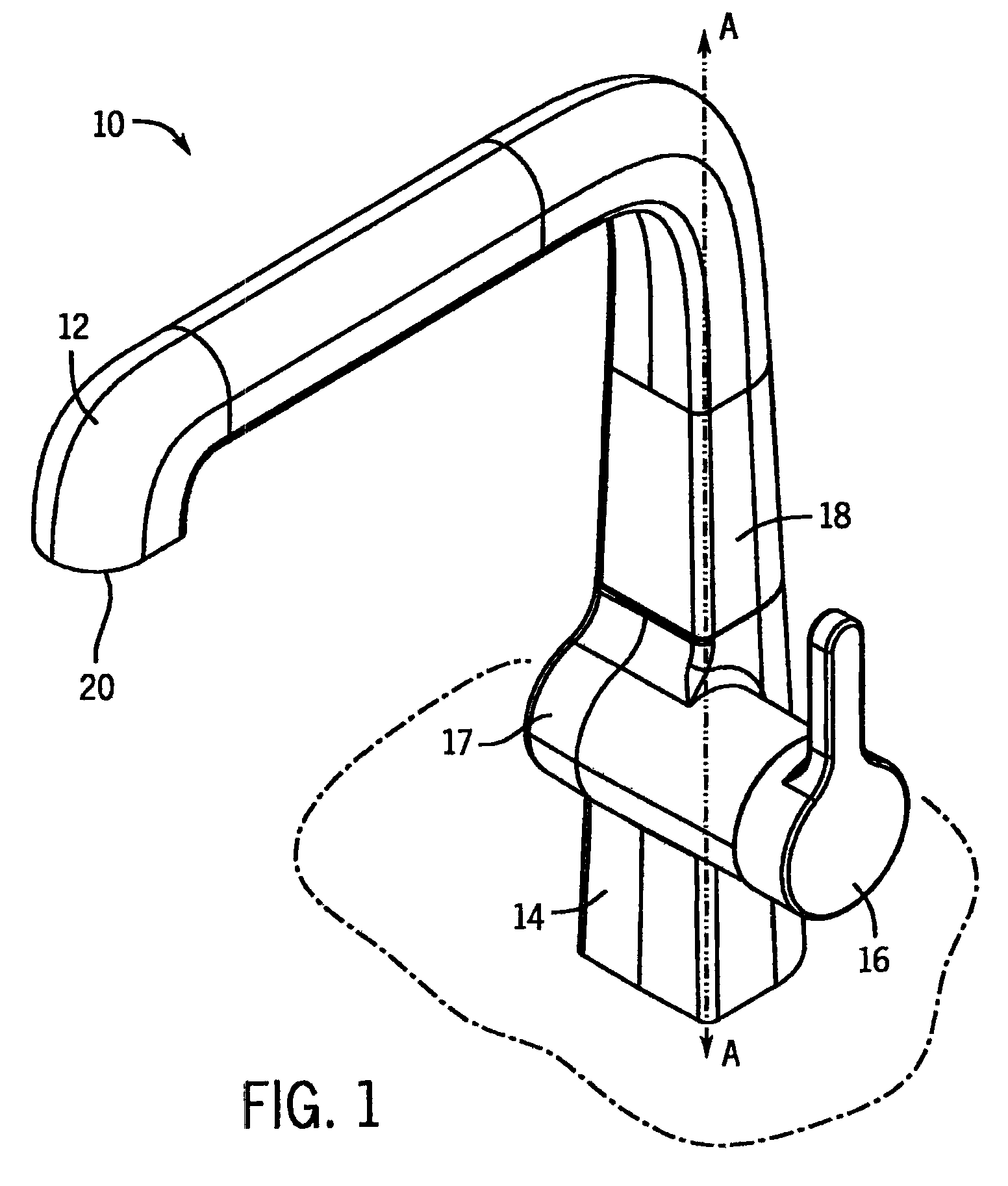
[0023]FIG. 1 illustrates a faucet 10 suitable for use adjacent a basin (e.g. a kitchen sink or other plumbing basin). The faucet 10 has a spout 12 extending up and out from a base 14. Extending out from a side of the base 14 is a control handle 16 that can be rotated or otherwise moved to control the flow and temperature of water from a mixing valve 17 through the spout 12.

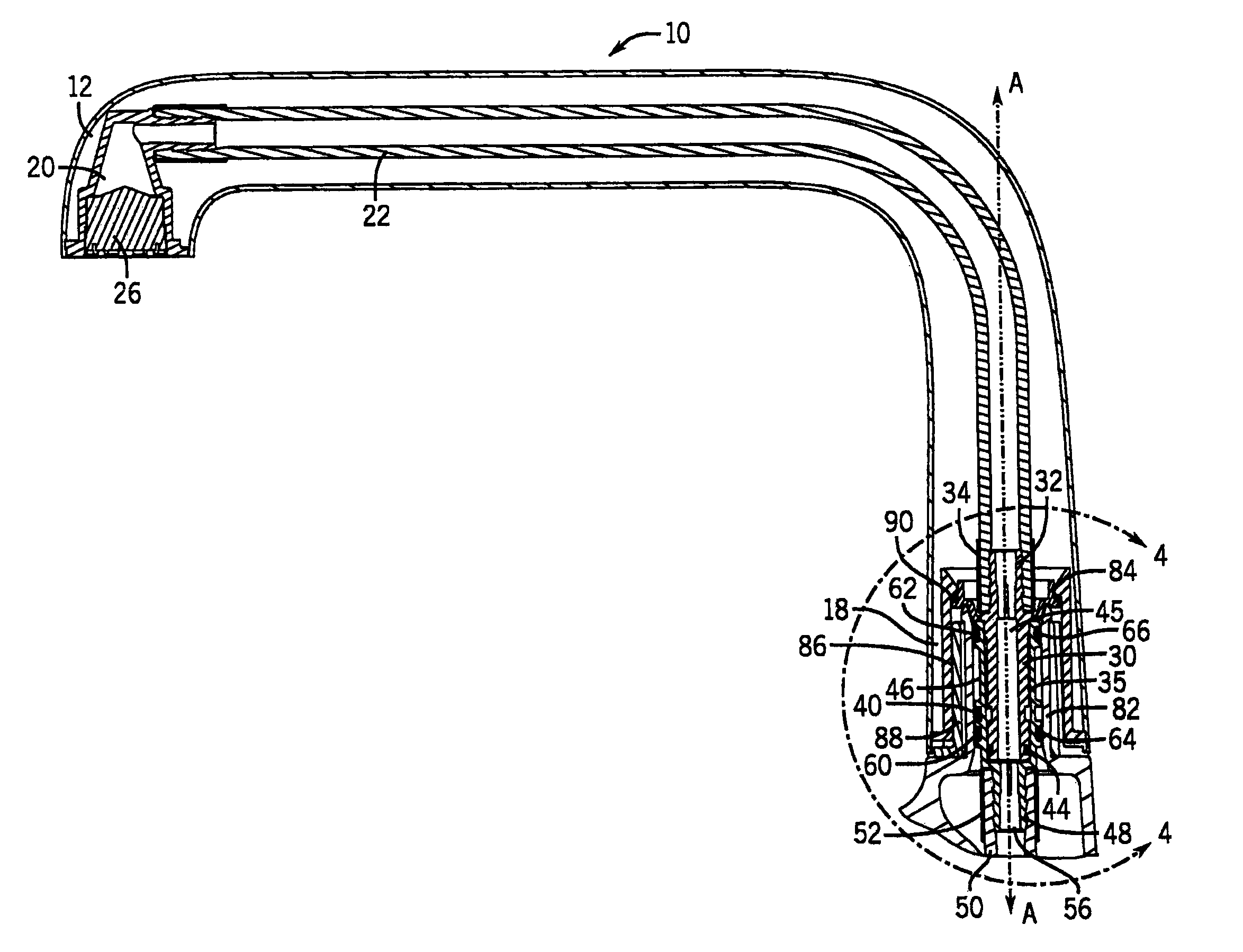
[0024]The spout 12 can be swiveled about an essentially vertical axis A relative to the base 14, about a connector assembly 18. This swiveling alters the location of the spout outlet 20 relative to the base 14, to direct the flow of water from the spout 12 to various locations or basins.

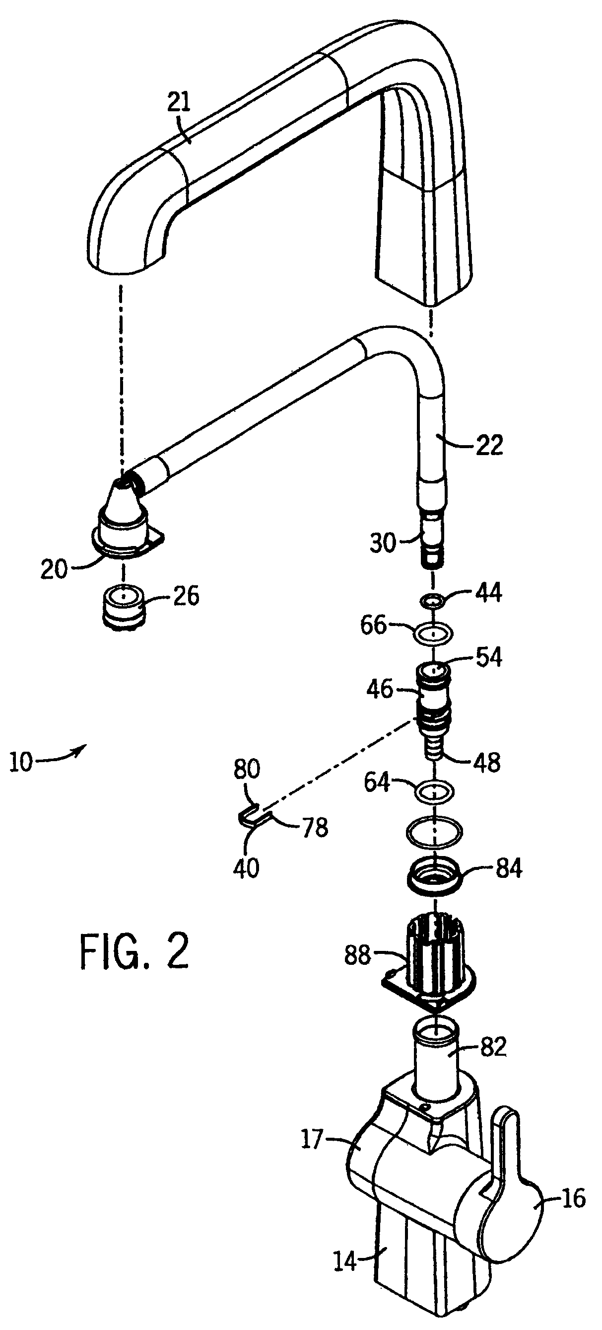
[0025]Now referring more to FIGS. 2, 3 and 4, there is shown a spout housing 21 containing a polymeric tube 22 having on one end an outlet linked to aerator 26. The other end of the polymeric tube 22 is mounted to a male connector sleeve 30 that has a barbed portion 32 inserted into the tube 22.

[0026]The barbed portion 32 is furthe...


PUM


Abstract

A faucet assembly is disclosed having internal carrier tubes, where the faucet spout can swivel relative to a faucet base without stressing the tubes. One tube connects a mixing valve to a connector sleeve. Another tube connects a spout outlet to another connector sleeve. The connector sleeves telescope within each other, have a seal there between, and are provided with a clip structure to hold them axially together while permitting relative rotation there between.

Description

CROSS-REFERENCE TO RELATED APPLICATION[0001]This application claims priority based on U.S. provisional application 61 / 027,888 filed Feb. 12, 2008.STATEMENT OF FEDERALLY SPONSORED RESEARCH OR DEVELOPMENT[0002]Not applicable.BACKGROUND OF THE INVENTION[0003]The present invention relates to faucets having swiveling spouts. More particularly it relates to structures for accommodating an internal tubing carrying water from a mixing valve to the spout outlet in such a swiveling spout.[0004]Many sinks have faucets positioned at the rearward end thereof, or immediately behind the sink. Such sinks may have relatively wide single basins, or may have multiple basins. Thus, it is often desirable for a faucet spout used therewith to be able to swivel so as to be able to direct water between multiple basins, or to a specific part of a wide basin.[0005]Even where a basin is not very large, it may be desirable to direct water to a pot or other reservoir positioned in the basin. Again, swiveling of ...

Claims


Application Information

Patent Timeline
Patent Type & Authority Patents(United States)
IPC IPC(8): B05B15/08F16L23/00F16B13/00F16K21/00E03C1/04B05B15/68
CPCF17D1/08E03C1/0404Y10T137/9464
Inventor ESCHE, JOHN C.BARES, WILLIAM R.
Owner KOHLER CO
Why Eureka
Try Eureka