Wall block with barrier member

a technology of wall blocks and barrier members, which is applied in the field of manufactured blocks, can solve the problems of increasing the labor costs of building a wall out of such blocks, requiring rather large blocks for retaining walls for large-scale applications, and increasing the labor costs of building walls out of such blocks

Active Publication Date: 2013-04-30
MORTARLESS TECH
View PDF34 Cites 11 Cited by
  • Summary
  • Abstract
  • Description
  • Claims
  • Application Information

AI Technical Summary

Benefits of technology

[0008]A retaining wall block can include a top surface and opposing bottom surface, a front surface and opposing rear surface, and first and second opposing side surfaces. A projection can extend downwardly from the bottom surface and can include a forwardly facing indexing surface oriented generally parallel with the front surface of the block. The indexing surface can be configured to engage a rearwardly facing surface of a block in a lower course of blocks. The block can also include a pair of spaced apart key slots defined in the rear surface. Each key slot can include an enlarged interlocking portion and a throat portion extending from the interlocking portion to the rear surface. An assembly can be created whereby a pair of correspondingly shaped keys of an elongate barrier member are engaged with key slots of block so as to inhibit rearward horizontal displacement of the keys within the key slots. Elongate barrier member can include a body presenting an inner surface and an outer surface and a pair of opposing ends, each opposing end defined one of the keys. The inner surface of the barrier member and the rear surface of the block can together define a core region for receiving fill material.

Problems solved by technology

Retaining walls for large-scale applications can require rather large blocks.
However, large blocks make building a wall a much more arduous task due to their size and weight.
This tends to increase the labor costs associated with building a wall out of such blocks.
Larger blocks are also more expensive to make and ship.
Fewer blocks can be made at one time in a mold, so production is slower and more concrete mix must be used.
Also, due to weight and height restrictions on the trucks that transport the blocks, fewer larger blocks can be shipped at a time so transportation costs are increased.

Method used


Image

  • Wall block with barrier member
  • Wall block with barrier member
  • Wall block with barrier member

Examples


Embodiment Construction

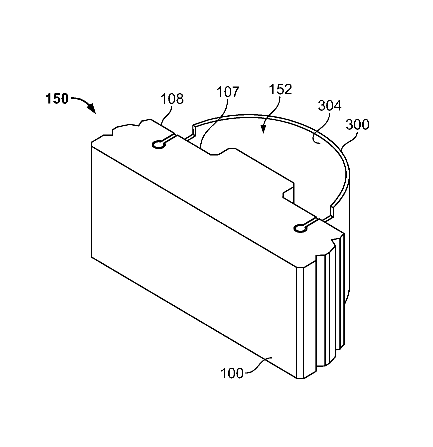
[0037]The use of wall blocks with attached barrier members enables wall systems to be constructed with decreased cost and labor. Walls having the same or more strength and stability as walls built with large retaining wall blocks can be built with much smaller wall blocks used with barrier members because blocks and barrier members function as a single unit and the banded region created by attaching barrier members to wall blocks provides a large amount of space that can be backfilled with crushed rock, dirt, or the like. Construction of such walls is much less labor intensive because of the reduced block size and weight and because barrier members are easily engaged with blocks. Substantial cost savings results because less concrete mixture is needed to form each block. Moreover, labor costs of building a wall with such blocks are reduced, more blocks can be shipped on a truck of the same size, and more blocks can be produced in the same size mold.

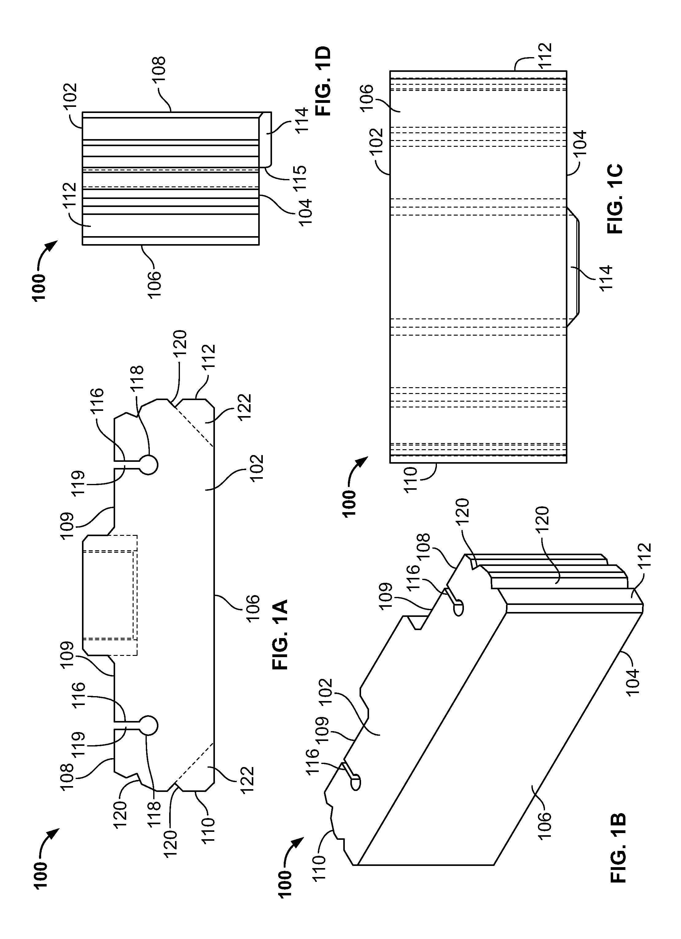
[0038]Referring to FIGS. 1A-1D, th...


PUM


Abstract

A retaining wall block can include a top surface and opposing bottom surface, a front surface and opposing rear surface, and first and second opposing side surfaces. A projection can extend downwardly from the bottom surface and can include a forwardly facing indexing surface oriented generally parallel with the front surface of the block. The indexing surface can be configured to engage a rearwardly facing surface of a block in a lower course of blocks. The block can also include a pair of spaced apart key slots defined in the rear surface. Each key slot can include an enlarged interlocking portion and a throat portion extending from the interlocking portion to the rear surface. An assembly can be created whereby a pair of correspondingly shaped keys of an elongate barrier member are engaged with key slots of block so as to inhibit rearward horizontal displacement of the keys within the key slots. Elongate barrier member can include a body presenting an inner surface and an outer surface and a pair of opposing ends, each opposing end defined one of the keys. The inner surface of the barrier member and the rear surface of the block can together define a core region for receiving fill material.

Description

CROSS-REFERENCE TO RELATED APPLICATION[0001]This application claims priority to U.S. patent application Ser. No. 61 / 175,716, filed on May 5, 2009, the entire contents of which are hereby incorporated by reference.TECHNICAL FIELD[0002]This document relates generally to retaining walls. More particularly, this document relates to manufactured blocks that are used to construct mortarless retaining walls.BACKGROUND INFORMATION[0003]Concrete blocks for free standing and retaining walls have been known and used for many years. They can be both functional and decorative, and range from small gardening applications to large-scale construction projects. Such walls are typically used to form horizontal surfaces or terraces by providing a generally vertically extending barrier behind which backfill may be deposited. Such walls reduce erosion and slumping, maximize land use, and can provide an attractive and decorative appearance.[0004]Retaining walls can be constructed from stackable concrete ...

Claims


Application Information

Patent Timeline
Patent Type & Authority Patents(United States)
IPC IPC(8): E02D29/02
CPCE04C1/395E04B2002/0243
Inventor PRICE, BRIAN A
Owner MORTARLESS TECH
Why Eureka
Try Eureka