Fan assembly

a technology of fan assembly and rotating blades, which is applied in the direction of motors, liquid fuel engines, non-positive displacement pumps, etc., can solve the problems of uneven or choppy air flow produced by the rotating blades of the fan, uncomfortable for users, and general uneven air flow

Active Publication Date: 2013-04-30
DYSON TECH LTD
View PDF394 Cites 19 Cited by
  • Summary
  • Abstract
  • Description
  • Claims
  • Application Information

AI Technical Summary

Benefits of technology

[0010]Some noise and motor vibration is reflected from the inner walls of the outer casing and the impeller housing. A silencing member located within the outer casing, particularly when located beneath the air inlet of the impeller housing, can absorb sound and noise within the outer casing. The arrangement of the silencing member spaced from the air inlet along the said axis by a distance in the range from 5 mm to 60 mm minimises the distance between the silencing member and the air inlet of the impeller housing without restricting the flow of air into the impeller housing. The arrangement can enable sufficient air to be drawn into the base to provide an unrestricted inflow of air to the impeller and the fan assembly. The side wall preferably comprises a plurality of air inlets. Locating air inlets around the base provides flexibility in the arrangement of the base and the nozzle, and enables air to flow into the base from a variety of points so that more air can flow into the assembly as a whole.
[0028]Preferably, the mouth of the nozzle extends about the opening, and is preferably annular. Preferably the nozzle extends about the opening by a distance in the range from 50 to 250 cm. The nozzle preferably comprises at least one wall defining the interior passage and the mouth, and wherein said at least one wall comprises opposing surfaces defining the mouth. Preferably, the mouth has an outlet, and the spacing between the opposing surfaces at the outlet of the mouth is in the range from 0.5 mm to 5 mm, more preferably in the range from 0.5 mm to 1.5 mm. The nozzle may preferably comprise an inner casing section and an outer casing section which define the mouth of the nozzle. Each section is preferably formed from a respective annular member, but each section may be provided by a plurality of members connected together or otherwise assembled to form that section. The outer casing section is preferably shaped so as to partially overlap the inner casing section. This can enable an outlet of the mouth to be defined between overlapping portions of the external surface of the inner casing section and the internal surface of the outer casing section of the nozzle. The nozzle may comprise a plurality of spacers for urging apart the overlapping portions of the inner casing section and the outer casing section of the nozzle. This can assist in maintaining a substantially uniform outlet width about the opening. The spacers are preferably evenly spaced along the outlet.

Problems solved by technology

A disadvantage of this type of fan is that the air flow produced by the rotating blades of the fan is generally not uniform.
These variations result in the generation of an uneven or ‘choppy’ air flow which can be felt as a series of pulses of air and which can be uncomfortable for a user.
In addition, this type of fan can be noisy and the noise generated may become intrusive with prolonged use in a domestic environment.
A further disadvantage is that the cooling effect created by the fan diminishes with distance from the user.
Any inefficiencies in the system, for example losses through the fan housing or disruptions in the air flow path, will reduce the air flow from the fan.
The high efficiency requirement restricts the options for the use of motors and other means for creating air flow.
This type of fan can be noisy as vibrations generated by the motor and impeller and any turbulence in the air flow tend to be transmitted and amplified.

Method used


Image

  • Fan assembly
  • Fan assembly
  • Fan assembly

Examples


Embodiment Construction

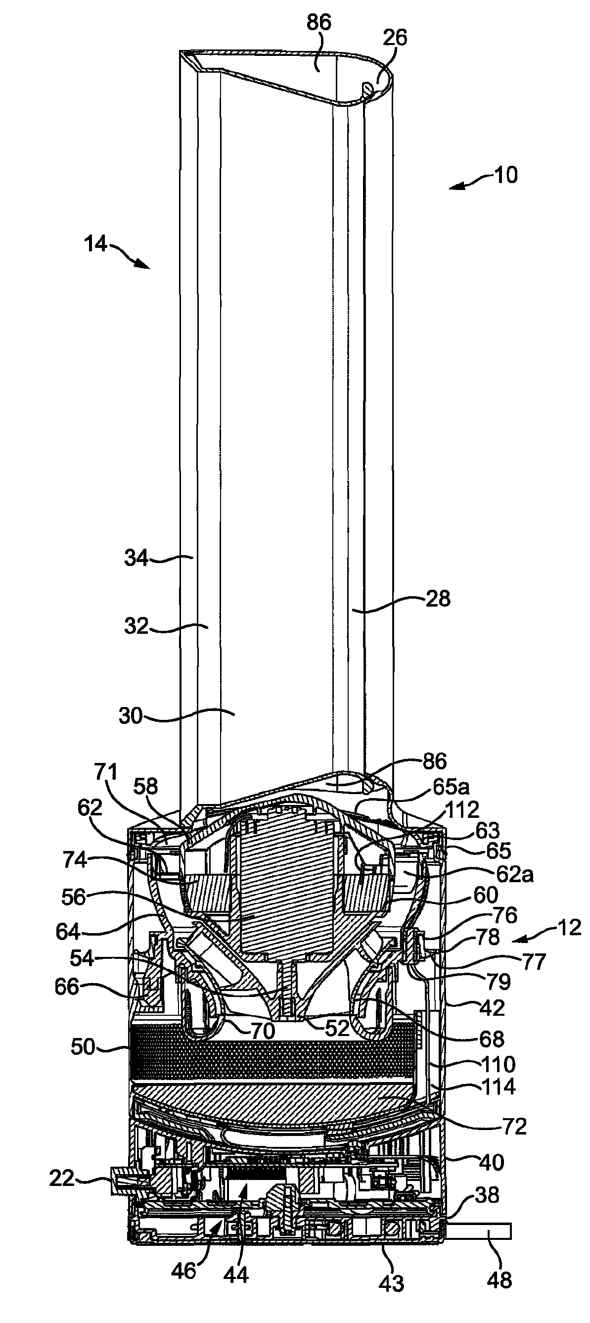
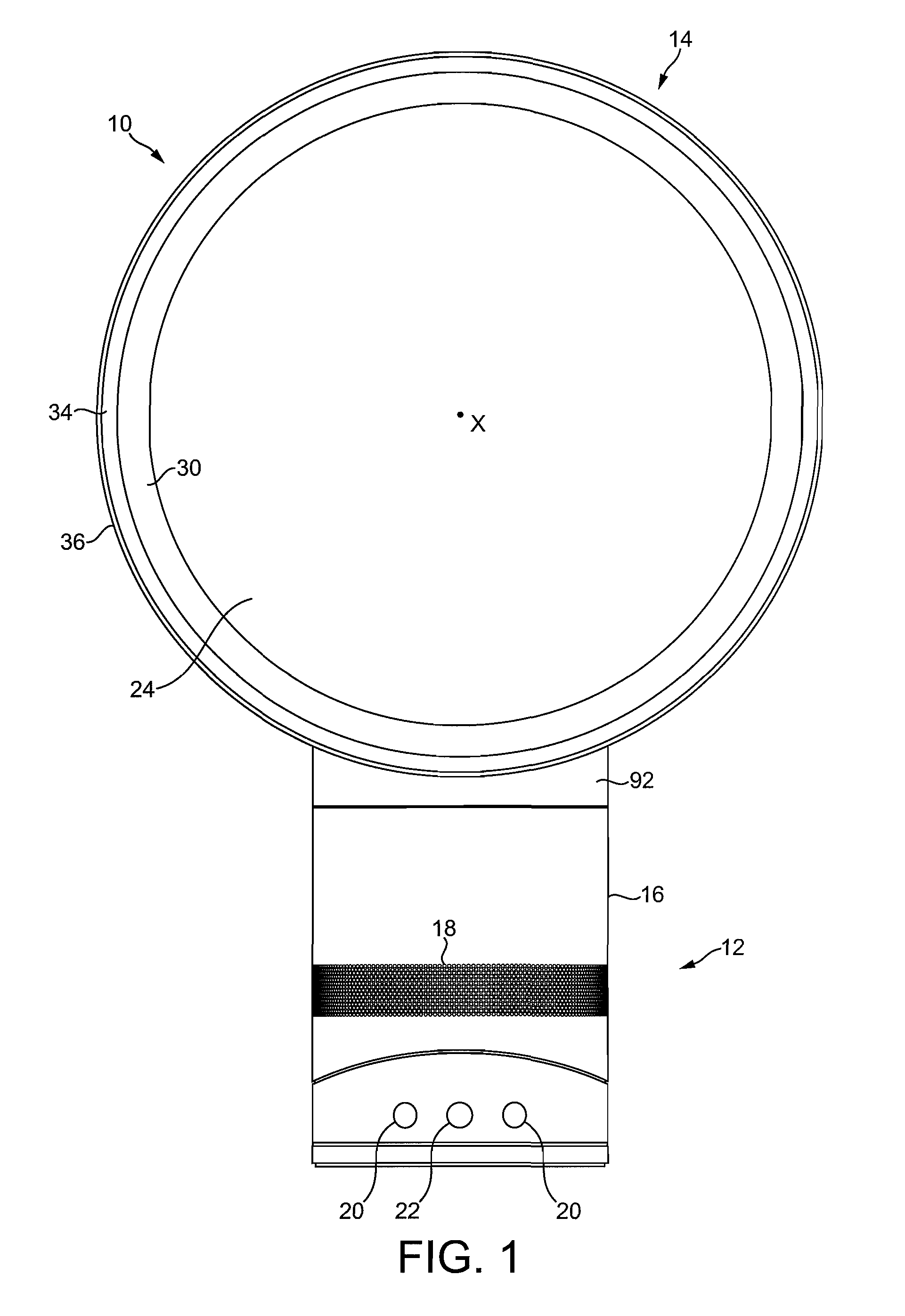
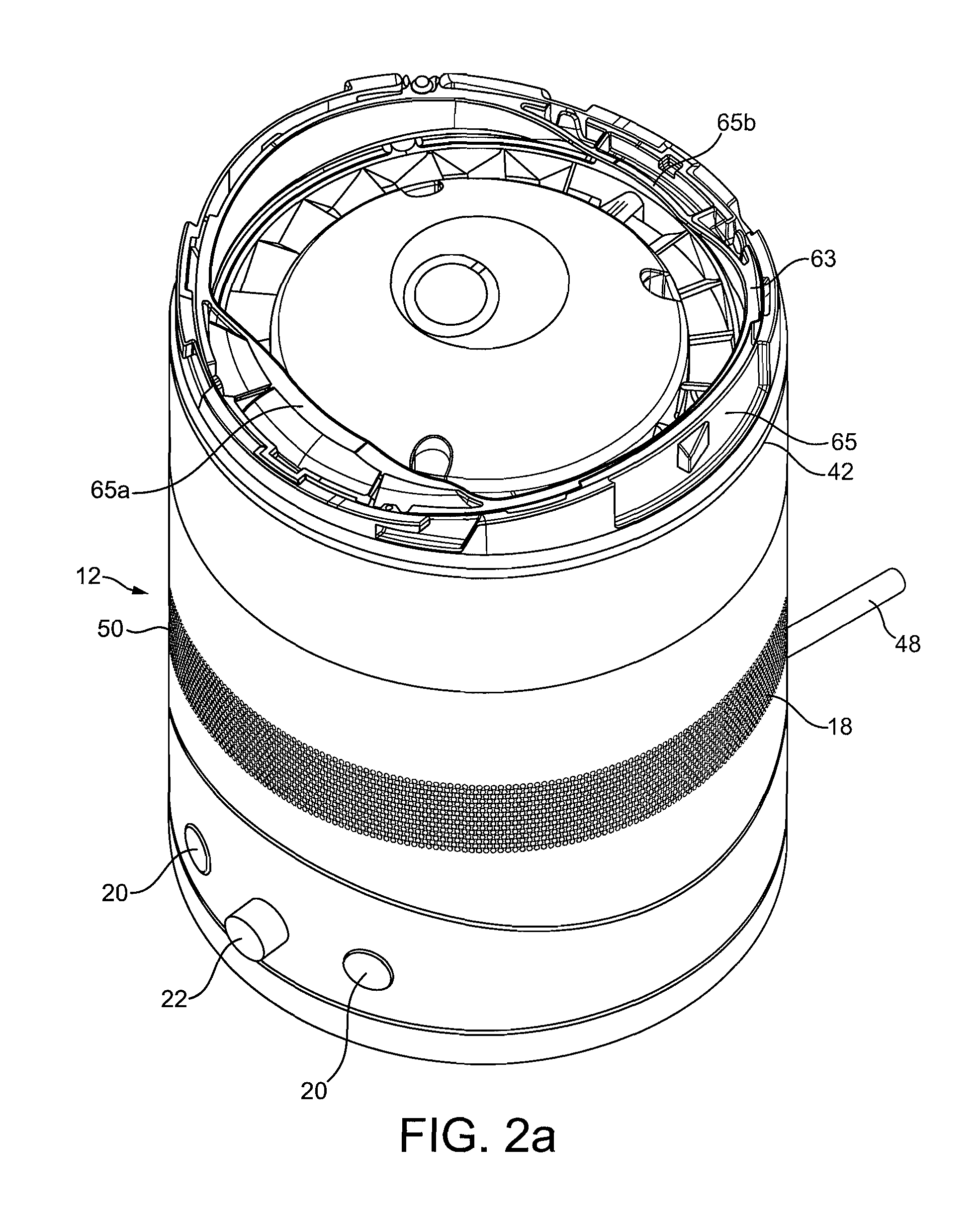
[0050]FIG. 1 is a front view of a fan assembly 10. The fan assembly 10 is preferably in the form of a bladeless fan assembly comprising a base 12 and a nozzle 14 mounted on and supported by the base 12. With reference to FIG. 2(a), the base 12 comprises a substantially cylindrical outer casing 16 having a plurality of air inlets 18 in the form of apertures located in the outer casing 16 and through which a primary air flow is drawn into the base 12 from the external environment. The base 12 further comprises a plurality of user-operable buttons 20 and a user-operable dial 22 for controlling the operation of the fan assembly 10. In this example the base 12 has a height in the range from 200 to 300 mm, and the outer casing 16 has an external diameter in the range from 100 to 200 mm.

[0051]With reference also to FIG. 2(b), the nozzle 14 has an annular shape and defines a central opening 24. The nozzle 14 has a height in the range from 200 to 400 mm. The nozzle 14 comprises a mouth 26 lo...


PUM


Abstract

A fan assembly for creating an air current includes a nozzle mounted on a base. The base includes an outer casing, a silencing member housed within the outer casing, an impeller housing located within the outer casing, the impeller housing having an air inlet and an air outlet, an impeller located within the impeller housing and a motor for driving the impeller about an axis to create an air flow through the impeller housing. The nozzle includes an interior passage for receiving the air flow from the air outlet of the impeller housing and a mouth through which the air flow is emitted from the fan assembly. The silencing member is located beneath the air inlet of the impeller housing and is spaced from the air inlet along said axis by a distance in the range from 5 to 60 mm.

Description

REFERENCE TO RELATED APPLICATIONS[0001]This application claims the priority of United Kingdom Application Nos. 0903671.6 and 0903673.2, filed 4 Mar. 2009, the entire contents of which are incorporated herein by reference.FIELD OF THE INVENTION[0002]The present invention relates to a fan assembly. Particularly, but not exclusively, the present invention relates to a domestic fan, such as a desk fan, for creating air circulation and air current in a room, in an office or other domestic environment.BACKGROUND OF THE INVENTION[0003]A conventional domestic fan typically includes a set of blades or vanes mounted for rotation about an axis, and drive apparatus for rotating the set of blades to generate an air flow. The movement and circulation of the air flow creates a ‘wind chill’ or breeze and, as a result, the user experiences a cooling effect as heat is dissipated through convection and evaporation.[0004]Such fans are available in a variety of sizes and shapes. For example, a ceiling f...

Claims


Application Information

Patent Timeline
Patent Type & Authority Patents(United States)
IPC IPC(8): F04D29/66
CPCF04D25/08F04D29/626F04D29/664F04F5/16F04D29/62F04D29/66
Inventor COOKSON, MATTHEWSIMMONDS, KEVIN JOHNNICOLAS, FREDERIC
Owner DYSON TECH LTD
Why Eureka
Try Eureka