Internal combustion engine fuel injection control method

a technology for fuel injection and combustion engines, applied in electrical control, process and machine control, instruments, etc., can solve the problems of deterioration of low-temperature startability, deterioration of -gas cleanness, particular problems, etc., and achieve the improvement of low-temperature startability, gasoline mileage, and exhaust-gas cleanness.

Active Publication Date: 2013-04-30
MITSUBISHI ELECTRIC CORP
View PDF18 Cites 3 Cited by
  • Summary
  • Abstract
  • Description
  • Claims
  • Application Information

AI Technical Summary

Benefits of technology

[0011]The present invention has been implemented in order to solve the foregoing problems; the objective thereof is to provide an internal combustion engine fuel injection control method in which, even through relatively weak in-cylinder gas reverse flow, produced in normal valve overlap, to the intake air flow path, fuel adhesion to the wall face of the intake air flow path is prevented and evaporation of the fuel and the mixture of the fuel and air are facilitated, so that, in particular, low-temperature startability, gasoline mileage, and exhaust-gas cleanness are raised.
[0014]An internal combustion engine fuel injection control method of the present invention makes it possible that evaporation of fuel and mixture of fuel and air in accordance with the operation state of an internal combustion engine are facilitated with a simple means that is not accompanied by any extra control for opening / closing of an intake valve; therefore, because excellent startability can always be obtained, there is demonstrated an effect that gasoline mileage and exhaust-gas cleanness can be improved.

Problems solved by technology

In an internal combustion engine utilizing a method of injecting fuel into an intake air flow path, deterioration in low-temperature startability, gasoline mileage, exhaust-gas cleanness, which is caused through adhesion of the injected fuel onto the wall face of the intake air flow path, is of a particular problem.
However, in the case where that kind of fuel injection is performed in synchronization with intake-air inflow into a cylinder, unevaporated fuel particles directly flow into the cylinder; therefore, no fuel-air mixture suitable for combustion can be obtained by the time combustion starts, whereby deterioration in startability, gasoline mileage, and exhaust-gas cleanness is caused eventually.
As a result, no fuel-air mixture suitable for combustion can be obtained by the time the combustion starts, whereby deterioration in startability, gasoline mileage, and exhaust-gas cleanness is caused eventually.
However, in the case of normal valve overlap setting, the intake valve starts to open immediately before the piston reaches the top dead center of the exhaust stroke; therefore, there can be obtained only a little amount of reverse flow.
Because the inflow of the fuel that has adhered, for example, to the upstream wall face of the intake air flow path is delayed, the amount of fuel that is injected in a cycle does not coincide with the amount of fuel that substantially flows into the cylinder; therefore, there still remains the problem of deterioration in startability, gasoline mileage, and exhaust-gas cleanness.
Moreover, the rate of inert gas included in the in-cylinder gas that is blown back differs depending on the result of previous-cycle combustion; thus, when a greater amount of reverse flow is produced, especially, at the starting timing when the combustion condition is unstable, the fluctuation of substantial air-fuel ratio of a fuel-air mixture produced inside the cylinder becomes large, whereby deterioration in startability and exhaust-gas cleanness becomes more conspicuous.

Method used


Image

  • Internal combustion engine fuel injection control method
  • Internal combustion engine fuel injection control method
  • Internal combustion engine fuel injection control method

Examples


embodiment 1

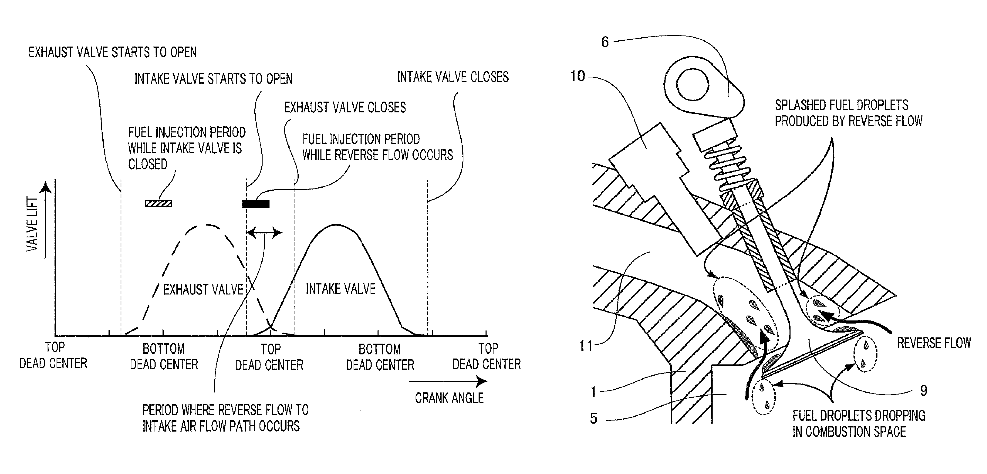
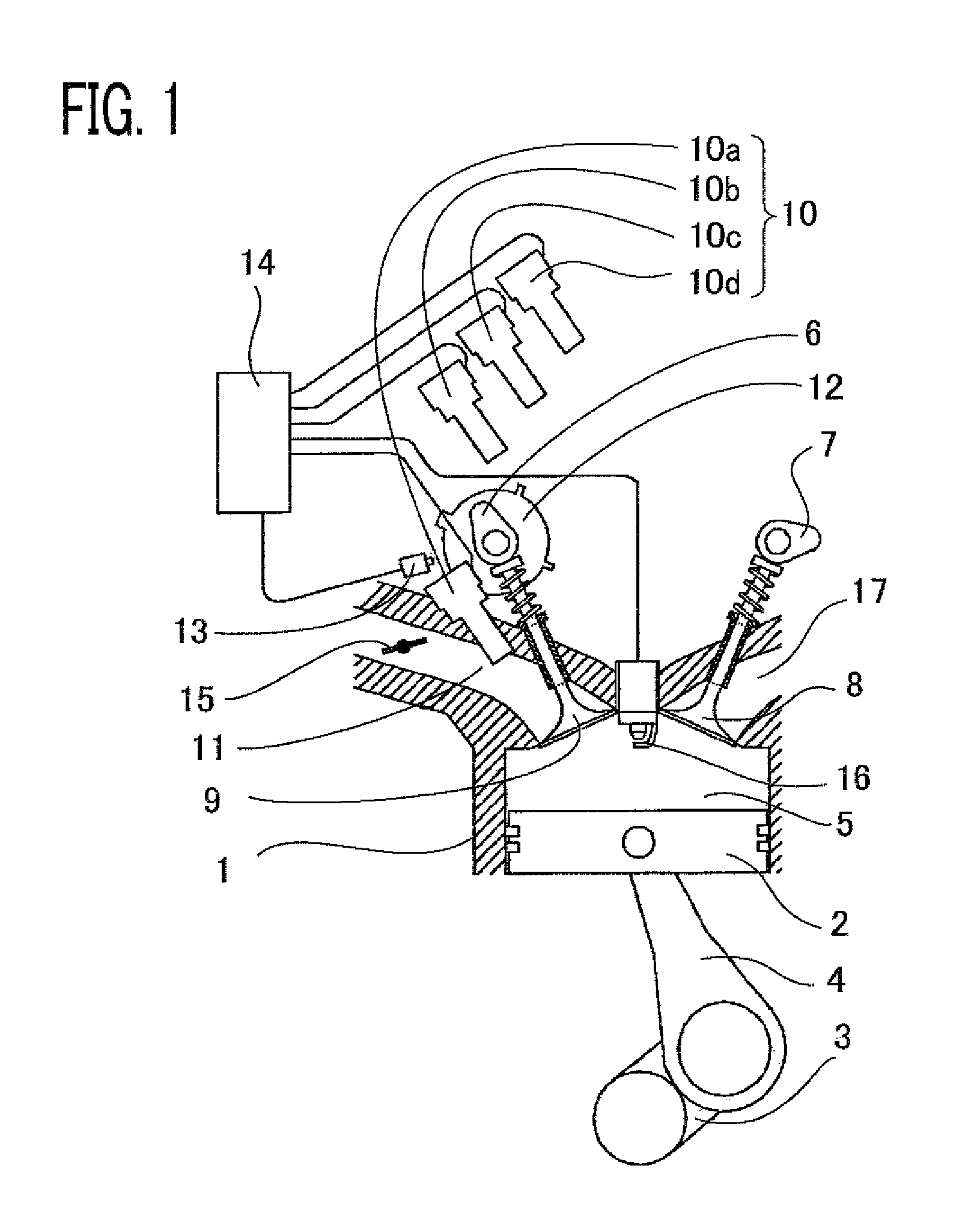
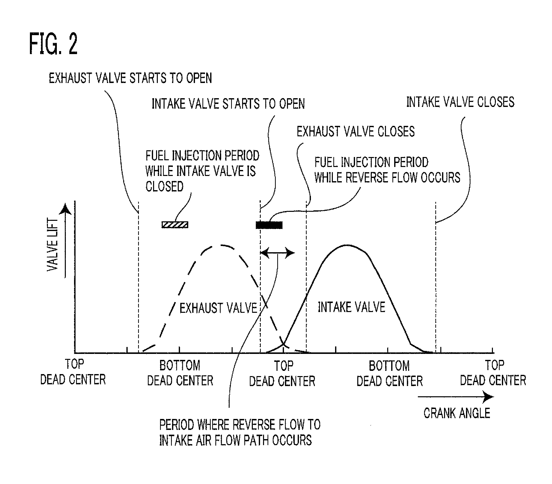
[0024]FIG. 1 is a configuration diagram of an internal combustion engine, provided with fuel injection valves for injecting fuel into the respective intake air flow paths of cylinders, that is based on an internal combustion engine fuel injection control method according to Embodiment 1 of the present invention. As illustrated in FIG. 1, the internal combustion engine according to Embodiment 1 of the present invention includes an internal combustion engine main body 1, a piston 2, a crank 3, a connecting rod 4, a combustion space 5, an intake cum 6, an exhaust cam 7, an exhaust valve 8, an intake valve 9, a fuel injection valve 10, an intake air flow path 11, a cam shaft rotation angle signal plate 12, a cam shaft rotation angle detector 13, an engine controller 14, a throttle valve 15, an ignition plug 16, and an exhaust manifold 17.

[0025]At first, with reference to FIG. 1, there will be explained the basic operation of an internal combustion engine utilizing a method of injecting ...

embodiment 2

[0055]In Embodiment 1 described above, there has been explained controlling operation in which, based on the coolant temperature and the exhaust-gas temperature, the proportion of the amount of fuel injected while the intake valve 9 is closed to the amount of fuel injected during the reverse flow period is calculated; however, Embodiment 2 of the present invention is to provide a specific method for fuel injection control in which the proportion of the amount of fuel injected while the intake valve 9 is closed to the amount of fuel injected during reverse flow period is changed, based on the running time of engine operation and the cycle numbers of engine operation, instead of the exhaust-gas temperature. The method will be explained below with reference to FIGS. 7 and 8.

[0056]FIG. 7 is a flowchart, of Embodiment 2, representing the setting of fuel injection control based on the coolant temperature and the running time of engine operation or the cycle numbers of engine operation and...


PUM


Abstract

In an internal combustion engine provided with a fuel injection valve for injecting fuel into an intake air flow path for each cylinder, there is performed a plurality of fuel injections during one cycle for each cylinder, one injection thereof being performed in synchronization with a period during which an intake valve is being opened and reverse flow of in-cylinder gas into the intake air flow path occurs. In accordance with a measurement quantity that changes as the temperatures of the surface, at the intake air flow path, of the intake valve and the inner wall face of the intake air flow path change, there is set the proportion of the amount of fuel injected in synchronization with the period during which reverse flow occurs to the total amount of fuel injected in one cycle for each cylinder.

Description

BACKGROUND OF THE INVENTION[0001]1. Field of the Invention[0002]The present invention relates to an internal combustion engine fuel injection control method of raising mainly low-temperature startability, gasoline mileage, and exhaust-gas cleanness of an internal combustion engine where fuel is injected into an intake air flow path.[0003]2. Description of the Related Art[0004]In an internal combustion engine utilizing a method of injecting fuel into an intake air flow path, deterioration in low-temperature startability, gasoline mileage, exhaust-gas cleanness, which is caused through adhesion of the injected fuel onto the wall face of the intake air flow path, is of a particular problem.[0005]As prevention measures for fuel adhesion to the wall face of an intake air flow path, fuel injection directed to an intake valve is effective. However, in the case where that kind of fuel injection is performed in synchronization with intake-air inflow into a cylinder, unevaporated fuel particl...

Claims


Application Information

Patent Timeline
Patent Type & Authority Patents(United States)
IPC IPC(8): F02D41/30
CPCF02D35/025F02D41/047F02D41/062F02D41/401F02D41/403F02D2200/021Y02T10/44Y02T10/40
Inventor HONDA, TETSUYA
Owner MITSUBISHI ELECTRIC CORP
Why Eureka
Try Eureka