Collimator assembly

a collimator and assembly technology, applied in the direction of lighting support devices, instruments, lighting and heating apparatuses, etc., can solve the problems of increasing material consumption, increasing material costs and increasing mass on the vehicle, and collimator requires a large amount of manufacturing time and effort for press, so as to improve the visibility of the associated light source, reduce package size, and reduce the effect of package siz

Inactive Publication Date: 2013-05-07
VARROC LIGHTING SYST SRO
View PDF28 Cites 60 Cited by
  • Summary
  • Abstract
  • Description
  • Claims
  • Application Information

AI Technical Summary

Benefits of technology

[0009]The majority of the light emitted by the light source is aimed into a direction approximately parallel with the axis. The remainder of the light emitted by the light source is directed at wide angles, which improves the visibility of the associated light source from a wide range of viewing angles. When the subject invention is used in a lamp on an automobile, the associated lamp is more visible in a wide range of viewing angles. The lamp could be, for example, a brake lamp, a turn signal lamp, a low beam headlight lamp or a high beam headlight lamp.
[0010]The subject invention is also advantageous because it is capable of a reduced package size, specifically because it is capable of being flatter than the prior art collimator assemblies, yet achieves the requisite luminous intensity needed for automobile lamps. Further, the housing containing the collimator assembly can be smaller than the housings containing the prior art collimator assemblies. This results in material savings, weight savings and other cost savings. Reduced package size allows increased options for placement of a lamp assembly. The subject invention can be used with either a single light source, e.g. an LED, or with a plurality of light sources, e.g. a plurality of LEDs printed on a printed circuit board.

Problems solved by technology

The disadvantage of this solution is increased collimator depth, which leads to increased material consumption, increased material costs and increased mass on the vehicle.
Moreover, such a collimator requires a large amount of manufacturing time and effort for press-cooling to prevent unequal material shrinkage.
Even further, such collimators only guide the light in one direction and do not allow the light to spread over wide angles.
This is particularly disadvantageous when used in a signal lamp of a vehicle.

Method used


Image

  • Collimator assembly
  • Collimator assembly
  • Collimator assembly

Examples


Embodiment Construction

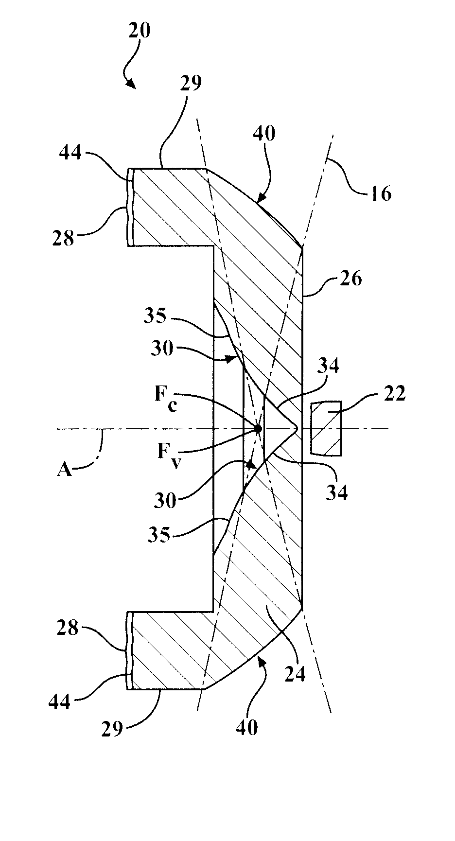
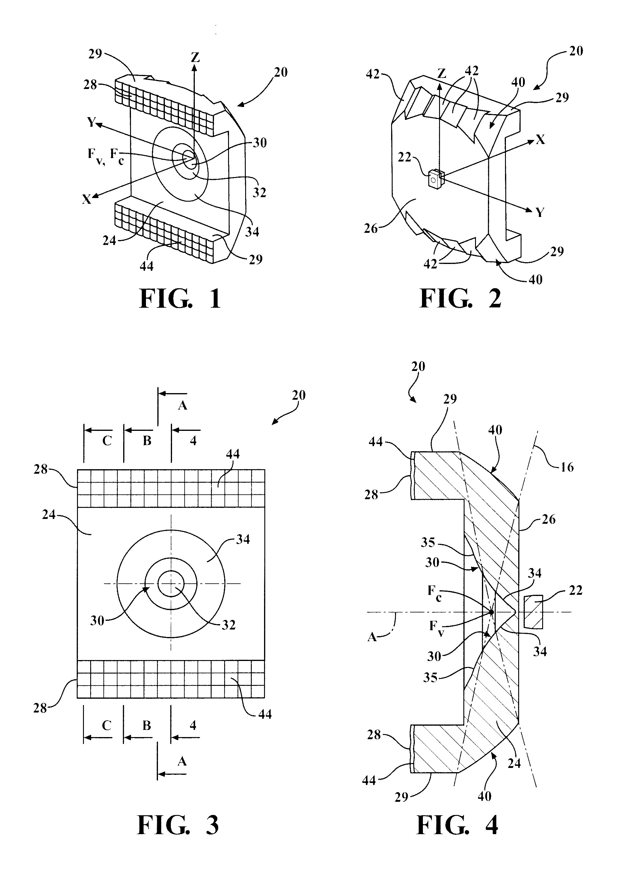
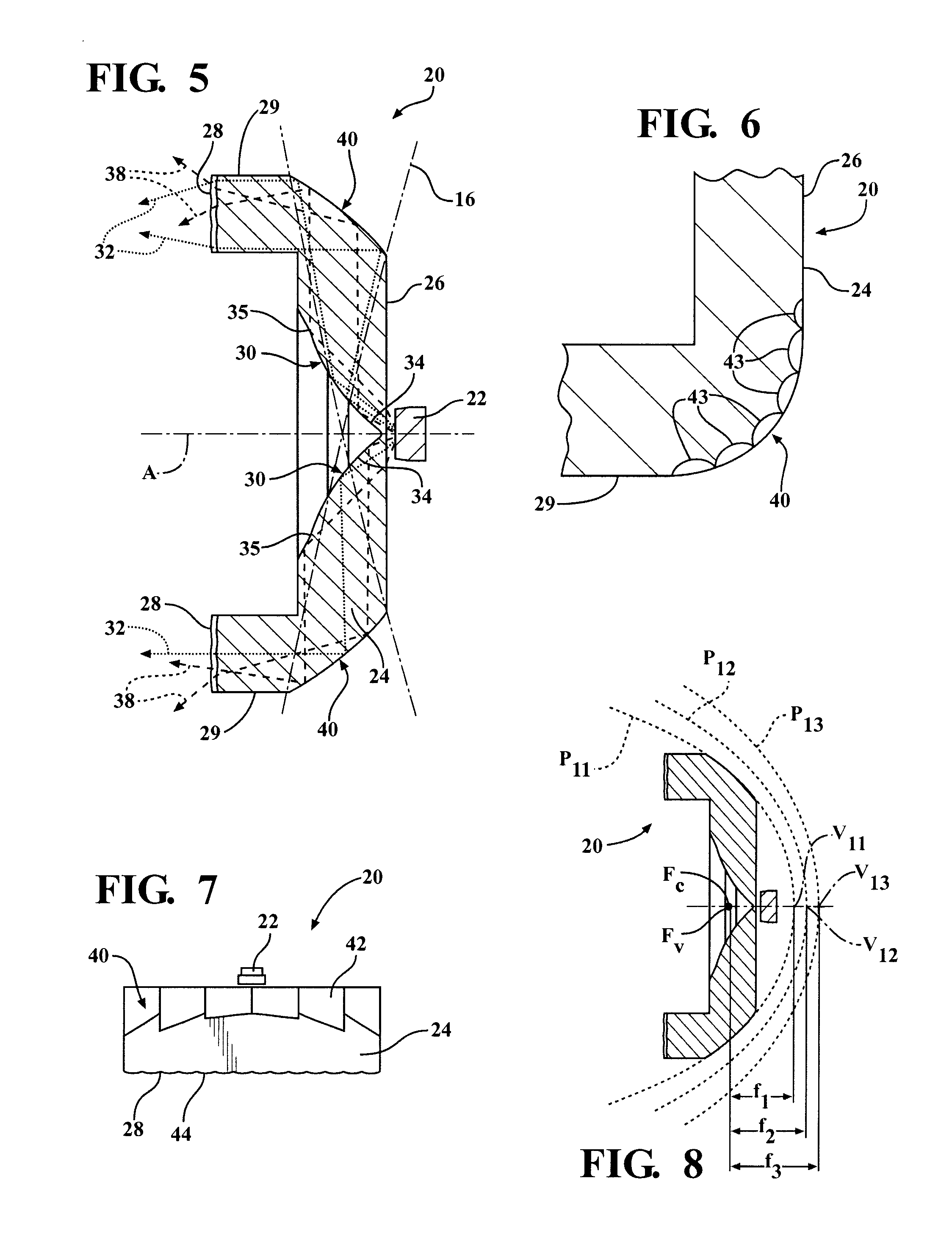
[0026]Referring to the Figures, wherein like numerals indicate corresponding parts throughout the several views, a collimator assembly 20 is generally shown in FIGS. 1-12. The collimator assembly 20 includes a light source 22 for emitting light and a light guide 24 for collimating the light. The light source 22 of the exemplary embodiment is a light emitting diode (LED) 22, though it should be appreciated that the light source 22 could be an incandescent bulb, a halogen bulb, a laser or any other light emitting device.

[0027]The light guide 24 defines an input surface 26 for receiving the light from the LED 22 and a pair of output surfaces 28, each disposed on a light pipe 29, for discharging the light. As best shown in FIG. 4, the light guide 24 is aligned along an axis A with the LED 22, and the input surface 26 faces the LED 22. The LED 22 is disposed between the light pipes 29. The light guide 24 includes a main reflective surface 30 (generally indicated) having a generally conic...


PUM


Abstract

A flat refractive collimator assembly including a light guide and a light source, for example, an LED. The sides of the light guide defines a collimating reflective surface having a paraboloidal shape with a collimating focal point placed on the axis of the light guide. The central portion of the light guide defines a main reflective surface having a virtual focal point, which is substantially similar to the collimating focal point. The collimating reflective surface is a paraboloidal surface or is formed as a plurality of paraboloidal segments having various focal lengths and having a common collimating focal point. The collimating reflective surface can also include spread optics.

Description

BACKGROUND OF THE INVENTION[0001]1. Field of the Invention[0002]The subject invention is related to a reflective collimator assembly for guiding light from a light source. More specifically, the subject invention is related to a reflective collimator assembly for guiding light from lamps on automobiles.[0003]2. Description of the Prior Art[0004]Typically, incandescent or halogen bulbs are used for vehicle lamps, e.g. turn signal lamps, brake lamps, low beam headlight lamps, high beam headlight lamps, etc. More recently, automobile makers have begun using light emitting diodes (LEDs) in automobile lamps for increased efficiency and reliability purposes. However, typically a collimator is required to guide the light emitted by the LEDs.[0005]One type of collimator is a non-focal optics based collimator. The disadvantage of this solution is increased collimator depth, which leads to increased material consumption, increased material costs and increased mass on the vehicle. Moreover, su...

Claims


Application Information

Patent Timeline
Patent Type & Authority Patents(United States)
IPC IPC(8): F21V7/06
CPCG02B6/0018G02B19/0028G02B19/0061G02B6/0036
Inventor ZWAK, ZDISLAVKROPAC, MIROSLAVCEJNEK, MILAN
Owner VARROC LIGHTING SYST SRO
Why Eureka
Try Eureka