Supercharge Your Innovation With Domain-Expert AI Agents!

Formation of patterned media by selective anodic removal followed by targeted trench backfill

a technology of selective anodic removal and trench backfill, which is applied in the field of formation of patterned media or discrete track media, can solve the problems of not being very selective in defining, not always achieving consistently higher bit densities, and complicated manufacturing methods of bpm and dtr

Active Publication Date: 2013-05-07
SEAGATE TECH LLC
View PDF10 Cites 1 Cited by
  • Summary
  • Abstract
  • Description
  • Claims
  • Application Information

AI Technical Summary

Benefits of technology

The patent describes a method for controlling the deposition of platinum (Pt) into a magnetic film layer on a substrate. The method involves removing cobalt (Co) from the magnetic film layer using anodic oxidation, which leaves Pt remaining in the grooves or trenches of the film layer. The remaining Pt can then enhance the corrosion rate of the remaining CoPt, especially when exposed to certain rinsing or drying steps. The method uses electrodeposition to backfill the non-magnetic matrix with other metals or alloys containing Pt, which can be carried out without disturbing the tracks or bits left from the oxidation step. This offers a cost-effective media fabrication process and ensures controlled deposition without requiring post-deposition lift-off or other processes. The method is particularly useful for manufacturing magnetic recording devices where trench depth needs to be controlled.

Problems solved by technology

However, manufacturing methods for BPM and DTR are complicated, expensive and inconsistent.
An issue with these types of etching is that they are not very selective in defining magnetic and non-magnetic regions on the magnetic film layer.
As a result, etching does not always result in consistently higher bit densities.
However, magnetic film layer modification using FIB is not readily scalable to mass production.

Method used


Image

  • Formation of patterned media by selective anodic removal followed by targeted trench backfill
  • Formation of patterned media by selective anodic removal followed by targeted trench backfill
  • Formation of patterned media by selective anodic removal followed by targeted trench backfill

Examples


Embodiment Construction

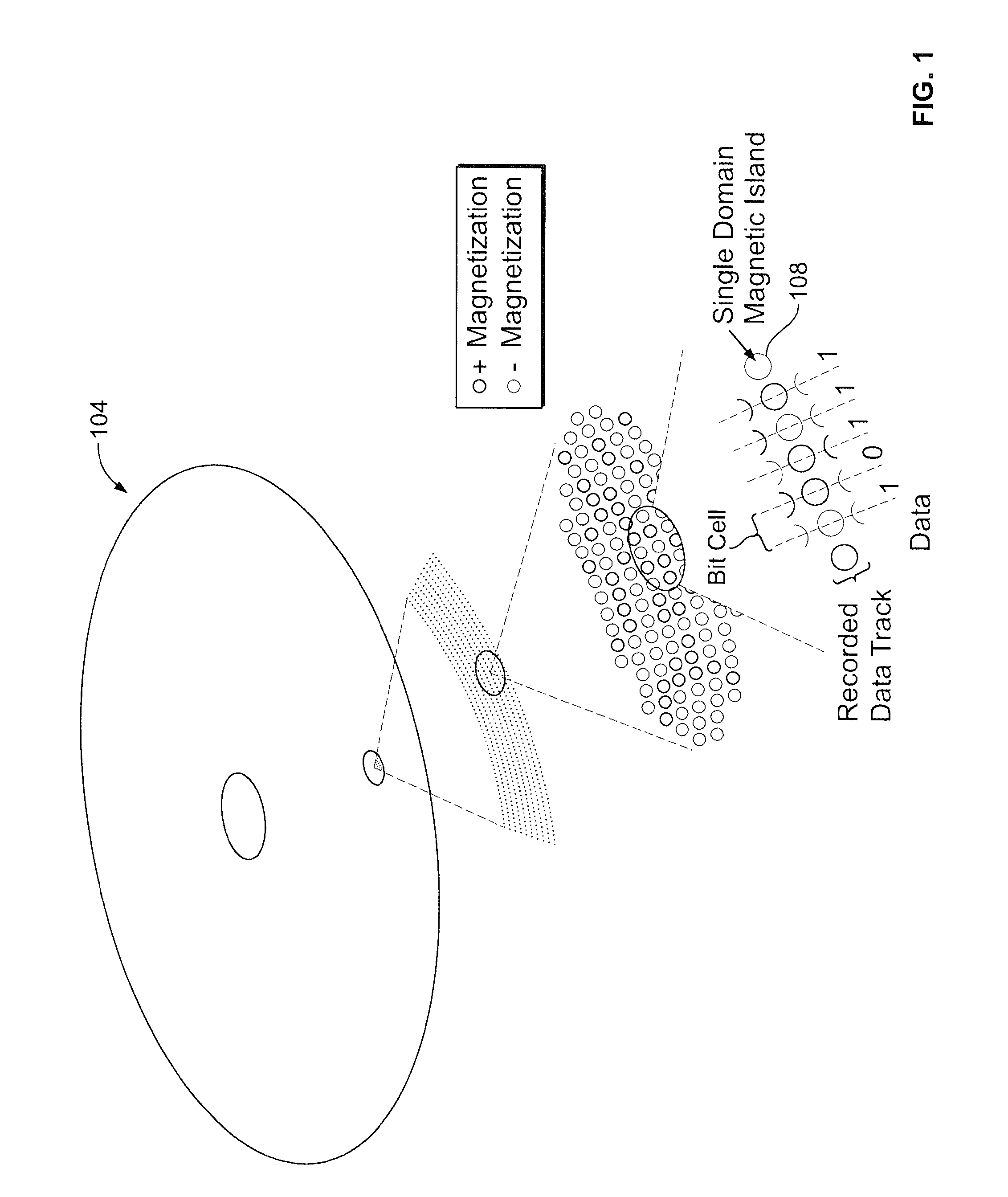
[0018]A method for forming patterned media is disclosed herein. The patterned medium is formed by selective anodic oxidation of a cobalt-containing magnetic film layer on the medium substrate, then depositing or backfilling a non-magnetic matrix in the regions of the cobalt-containing magnetic film layer where cobalt was removed. By way of example, FIG. 1 depicts an exemplary storage medium 104 comprising an array of magnetic dots 108 in a magnetic film layer. Each magnetic dot 108 is capable of storing a single bit of information. A typical magnetic film layer may be comprised of cobalt (Co) and platinum (Pt).

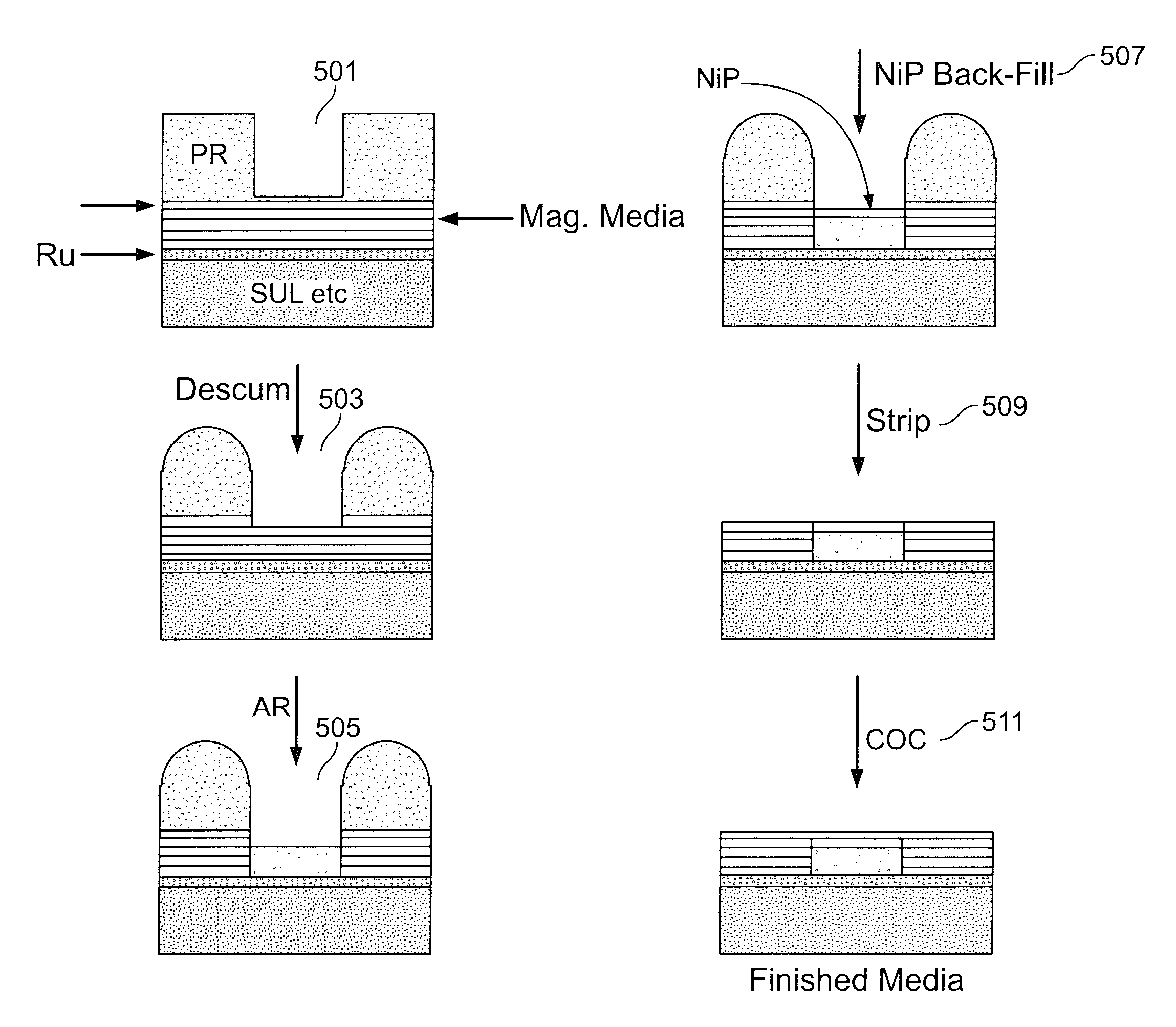
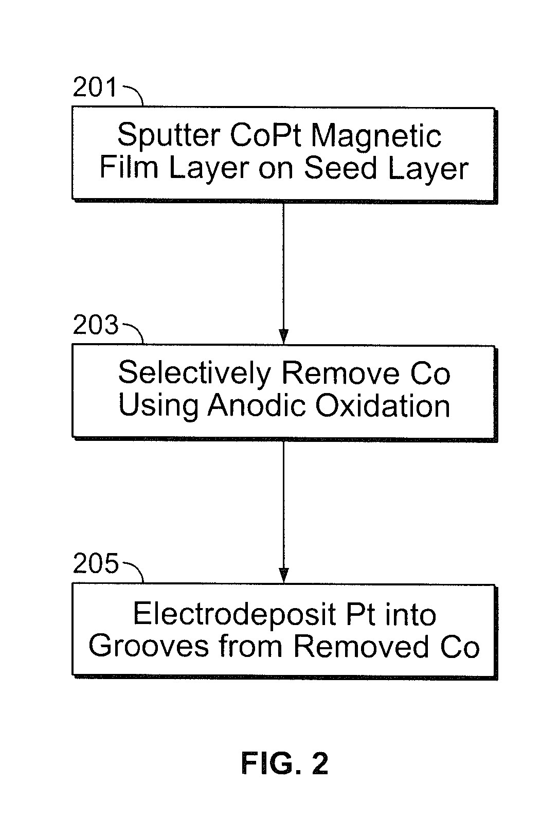
[0019]FIG. 2 is a flowchart illustrating the steps of an exemplary oxidation-reduction method in which the removal of cobalt from the media substrate and backfilled with a non-magnetic matrix in a single electrochemical cell, or “one-pot” method. As will be explained further below, the progress of the reaction may be attenuated by lowering the current applied to the single ele...


PUM

PropertyMeasurementUnit
diameteraaaaaaaaaa
pHaaaaaaaaaa
pHaaaaaaaaaa

Abstract

A method is disclosed for defining discrete magnetic and non-magnetic regions on the magnetic film layer of a storage media substrate. The method applies anodic oxidation of a cobalt-containing magnetic film layer to remove cobalt, followed by controlled deposition of a non-magnetic matrix into the regions where the cobalt has been removed. Deposition may either be electrodeposition, collimated vacuum deposition, or other methods depending upon the composition of the non-magnetic matrix being deposited. The method may be performed in a single electrochemical cell.

Description

FIELD[0001]This disclosure relates generally to the formation of patterned media or discrete track media for use in storage media. Specifically, this disclosure relates to the deposition of a non-magnetic matrix to form patterned media or discrete track media.BACKGROUND[0002]Bit patterned media (BPM) and discrete track media (DTR) are becoming more popular media for storage because of their inherent abilities to store more data in a smaller area. The goal of BPM and DTR and other patterned media is to increase bit density. However, manufacturing methods for BPM and DTR are complicated, expensive and inconsistent.[0003]BPM media are typically formed by using lithography to define the pattern on the media substrate. Once the pattern is defined, the translation of the pattern to the media substrate is typically an additive or subtractive process. An additive process, e.g., electrodeposition and lift-off, requires steps of creating a resist pattern and then depositing a magnetic film la...

Claims


Application Information

Patent Timeline
Patent Type & Authority Patents(United States)
IPC IPC(8): C25F3/02C25D5/02
CPCB82Y10/00C25D5/022C25D11/20C25D11/34G11B5/743G11B5/855G11B5/858G11B5/656G11B5/84C25F3/14G11B5/82Y10T428/24355G11B5/657
Inventor TAKAKOVIC, IBRORIEMER, STEVEGONG, JIEKIEF, MARK THOMASSUN, MING
Owner SEAGATE TECH LLC
Features
  • R&D
  • Intellectual Property
  • Life Sciences
  • Materials
  • Tech Scout
  • Unparalleled Data Quality
  • Higher Quality Content
  • 60% Fewer Hallucinations
Learn More