
Efficient illumination of large three dimensional environments

a three-dimensional environment and efficient technology, applied in the field of computer graphics, can solve the problems of inefficient illumination, sheer scale of the environment, and inability to model the history of each photon in this way at any reasonable rate, and achieve the effect of efficient determination of illumination

Active Publication Date: 2013-05-07
AECHELON TECH
View PDF8 Cites 21 Cited by
  • Summary
  • Abstract
  • Description
  • Claims
  • Application Information

AI Technical Summary

Benefits of technology

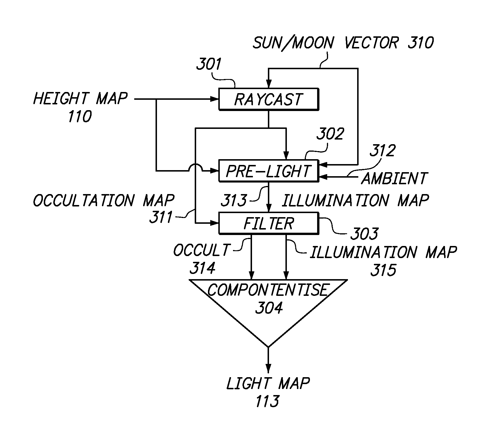
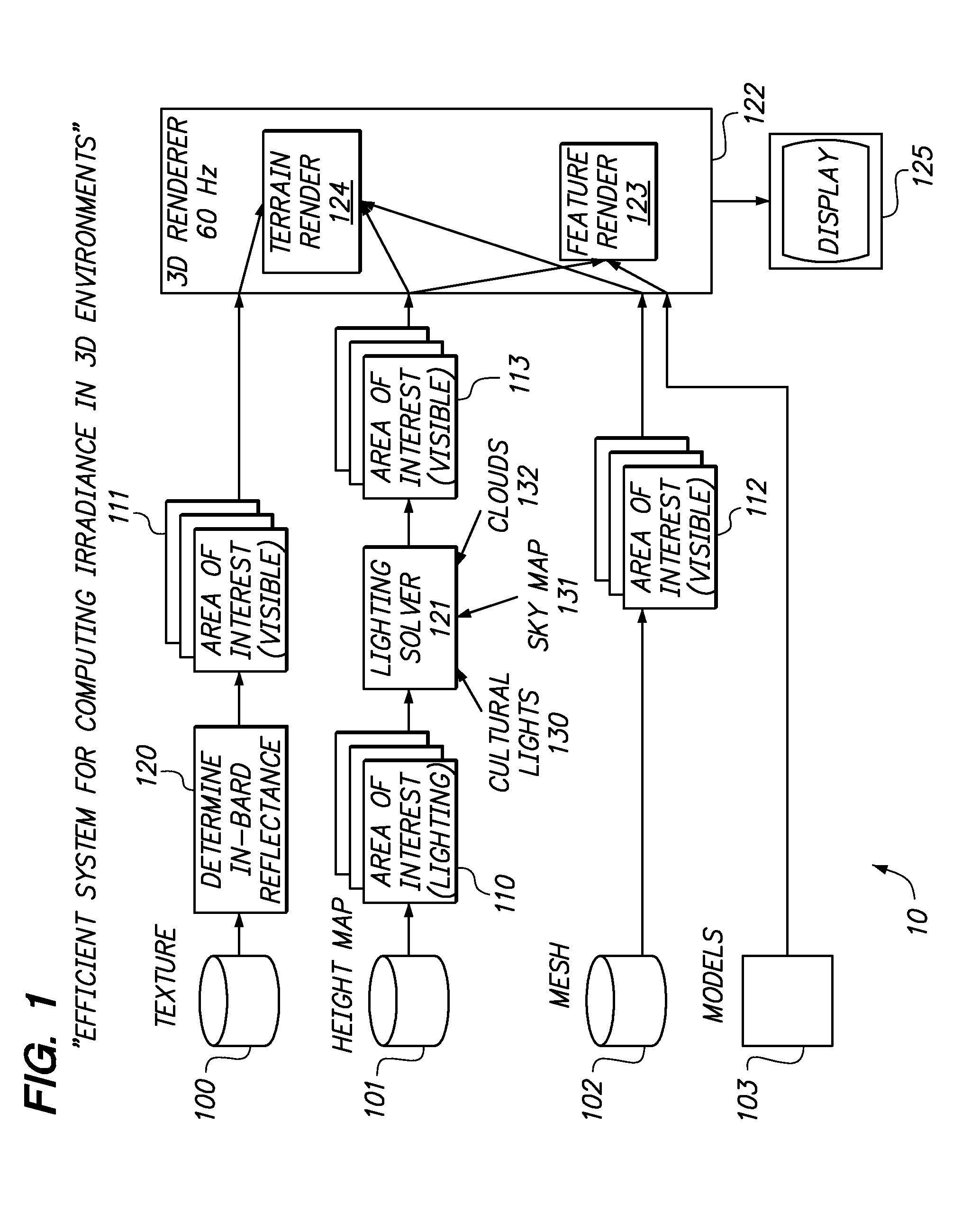
The present invention is efficient for determining lighting in large 3D environments, including shadowing. It uses a raster elevation map and a Lighting Solver to create an illumination map that is applied to terrain and features using a 3D Renderer. The Lighting Solver updates the illumination map as needed to reflect changes in illumination or movement of the visual area. Overall, this invention allows for better visualization of 3D environments and improved user experience.

Problems solved by technology

However, modeling the history of each photon in this way is computationally unfeasible at any reasonable rate.
For many applications, however, outdoor scenes cover very large areas (100,000 km2, for example), and the sheer scale of the environment presents unique challenges to efficient illumination.
Direct illumination is a fairly simple problem that scales linearly with the resolution of the display device, and therefore needs no special consideration for large environments.
Shadowing, however, is a much more computationally intensive problem, because, for each point in the scene, there are many points along the ray to the light source that may or may not be filled by terrain or other feature (such as a mountain).
Moreover, the complexity of the problem increases as the elevation angle of the sun / moon decreases, because the rays travel greater horizontal distances before rising above the tallest features in the scene.
In a statically shadowed environment, shadows are computed ahead of time, for a single (or a small number of) light position, and those shadows will be incorrect for any other time of day or positioning of objects and structures.
Over large areas, shadow mapping suffers from the limited precision of depth buffers and the limited size of the texture maps.
Setting this term can be very subjective and often cannot be constant over the shadow map area.
The preprocessing step is very computationally intense, however, and the parameters can require a great deal of extra storage in the 3D database and corresponding increased bandwidth to transmit them to the graphics engine.
While the math required for testing ray intersections is very simple, it has not historically been practical for real-time application over large areas due to the fact that the number of rays and potential intersections both increase geometrically with the size of the environment.
Shadowing effects can be also incorporated onto a light map, rendered using any of the previously described algorithms, but applying the shadowed light map to the object geometry can be challenging in many cases.

Method used


Image

  • Efficient illumination of large three dimensional environments
  • Efficient illumination of large three dimensional environments
  • Efficient illumination of large three dimensional environments

Examples


Embodiment Construction

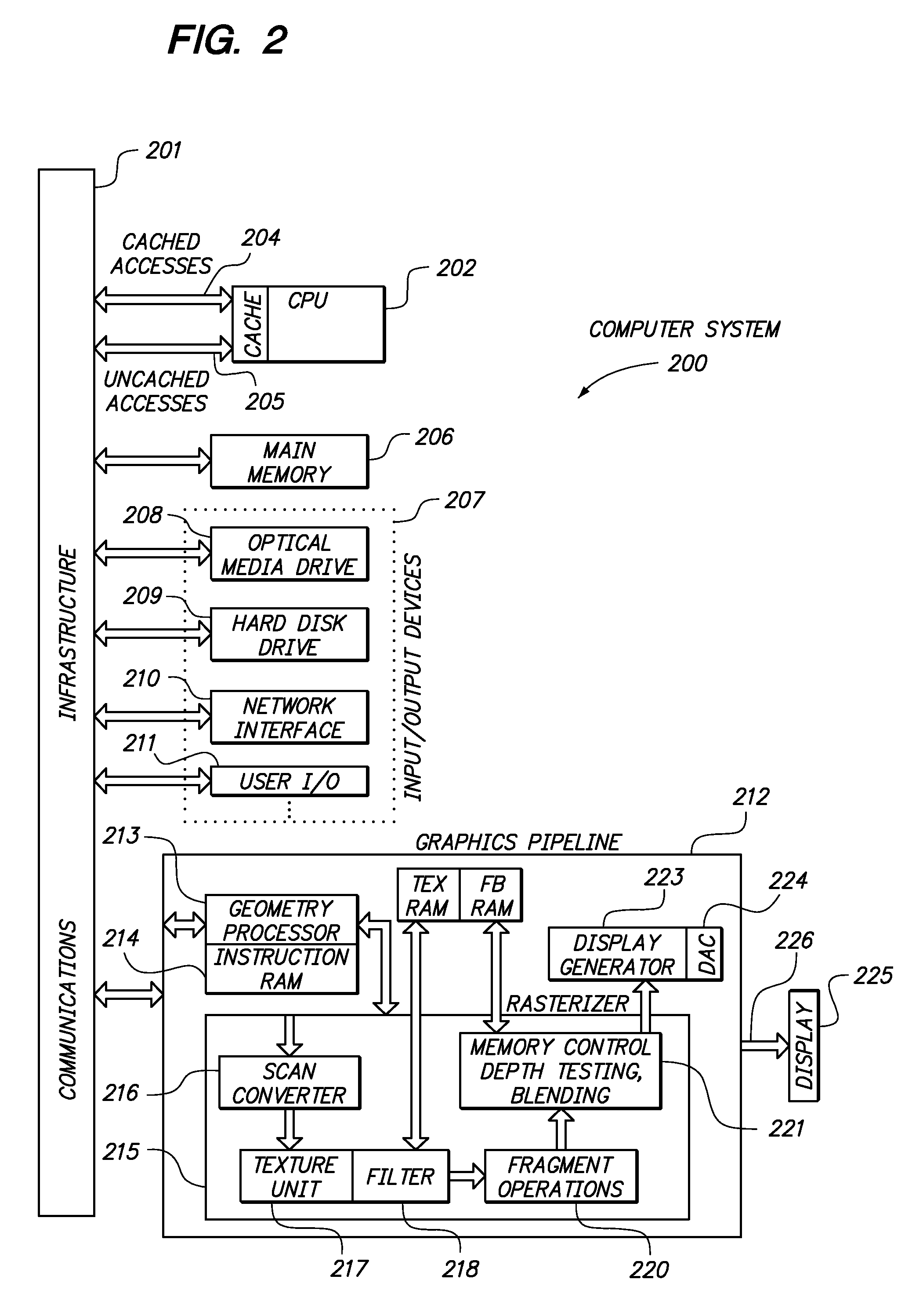
[0036]FIG. 2 depicts an example of a computer system 200 equipped with a three-dimensional graphics pipeline 212 in accordance with an embodiment of the present invention. The graphics pipeline is one embodiment of a three-dimensional renderer or a real-time three-dimensional renderer. Computer system 200 may be used to render all or part of a scene mapped in accordance with the present invention. This example computer system is illustrative of the context of the present invention and is not intended to limit the present invention. Computer system 200 is representative of both single and multi-processor computers.

[0037]Computer system 200 includes one or more central processing units (CPU), such as CPU 202, and one or more graphics subsystems, such as graphics pipeline 212. One or more CPUs 202 and one or more graphics pipelines 212 can execute software and / or hardware instructions to implement the graphics functionality described herein. Graphics pipeline 212 can be implemented, fo...


PUM


Abstract

Efficient determination of illumination over large 3D environments, including shadowing, is provided. Illumination, including shadows, is generated using a raster elevation map by a lighting solver. The lighting solver fetches the raster elevation map for an illumination area of interest at the paging rate and produces an illumination map that is applied to terrain and features by a 3D renderer. The lighting solver updates subsets of the illumination map as necessary to reflect changing illumination or movement of the visual area of interest.

Description

CROSS-REFERENCE TO RELATED APPLICATIONS[0001]This application claims the benefit of U.S. Provisional Application 60 / 890,596, filed on Feb. 19, 2007 and incorporated by reference herein in its entirety.BACKGROUND OF THE INVENTION[0002]1.Field of the Invention[0003]The present invention relates to the field of computer graphics, specifically to the illumination of large three-dimensional (3D) environments.[0004]2.Description of the Related Art[0005]Illumination has been one of the primary concerns in the field of 3D computer graphics since its inception. In order to realistically render a synthetic scene, one must not only capture the reflective properties of the various materials in the scene, but also characterize the illumination at each visible point in the scene. Ideally, this characterization would model every photon impacting that point in the 3D scene, including each photon's wavelength and direction of travel. To do this rigorously would mean tracing each photon's history, fr...

Claims


Application Information

Patent Timeline
IPC IPC(8): G06T15/50
CPCG06T15/506G06T15/80
Inventor MORGAN, DAVID L.SANZ-PASTOR, IGNACIOCASTELLAR, JAVIER
Owner AECHELON TECH
Learn More