Intramedullary nail with shape memory elements

a technology of shape memory and intramedullary nail, which is applied in the field of intramedullary nail, can solve the problems of not being able to guarantee the complete stabilisation of the nail inside the medullary canal, the x-ray technique is involved in the cumulative exposure of the operating staff, and the difficulty of x-rays, so as to achieve the effect of simple construction

Active Publication Date: 2013-05-14
ORTHOFIX SRL
View PDF5 Cites 31 Cited by
  • Summary
  • Abstract
  • Description
  • Claims
  • Application Information

AI Technical Summary

Benefits of technology

[0019]The solution idea at the basis of the present invention is that of providing a nail including an internal rod and an external sleeve and comprising shape memory elements associated to said rod; the rod having a very simple construction including seats for the memory elements just in the proximal and distal portions and keeping the shape elements in their seats by corresponding covers that are part of the rod. This allows realizing with only few components nails having shape memory elements laying on different planes without using bone screws for stabilizing the nail inside the medullary canal.

Problems solved by technology

Although still widely used those known nails have known drawbacks due to bone drillings performed for the bone screw insertion in correspondence with the holes of the inserted intramedullary nail.
Since the nail holes are no visible, X rays technique is involved with cumulative exposure of the operating staff and being quite awkward during the surgical operation.
For instance, the total missing of bone screws does not ensure complete stabilisation of the nail inside the medullary canal and against a high axial stress determined by the weight of a patient's body.
If such stress is applied the nail becomes unstable and might even compromise the process of osteosynthesis as well as causing anomalies in the healing process.
This solution simplifies the nail structure of the nails comprising only shape-memory material but it is still a compromise that require surgery for inserting the stop screw for stabilizing the nail inside the bone.

Method used


Image

  • Intramedullary nail with shape memory elements
  • Intramedullary nail with shape memory elements
  • Intramedullary nail with shape memory elements

Examples


Embodiment Construction

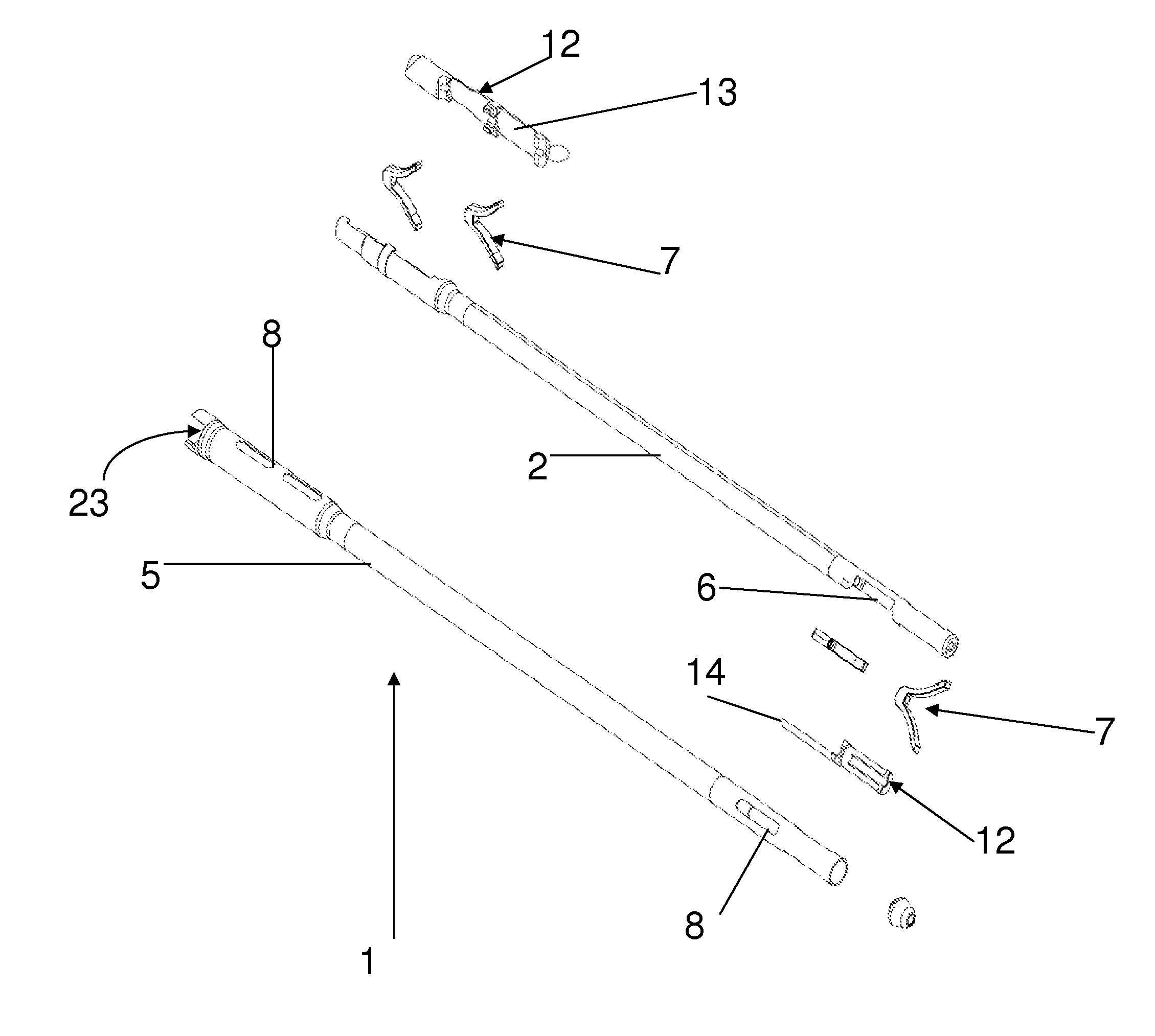
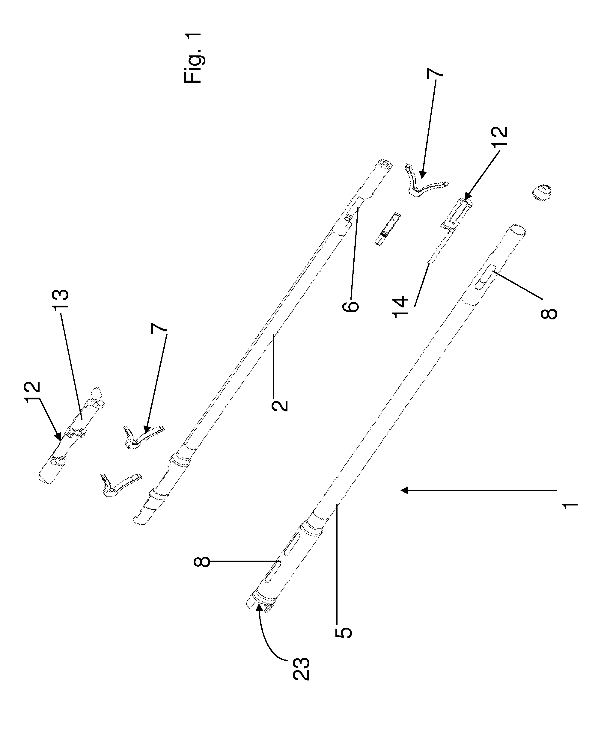
[0046]With reference to the aforementioned figures, 1 generally indicates an intramedullary nail in accordance with the present invention, intended to be inserted into a fractured long bone, for instance a femur.

[0047]In case of femoral nail, the nail 1 is provided with an anatomic shape having proximal bent of 5° to follow the shape of the femoral bone. So, the nail 1 and its main components are curved or bent so that the proximal end forms a small angle of 5° with the distal end.

[0048]The nail 1 comprises an inner rod 2 extending between a proximal end 3 and a distal end 4.

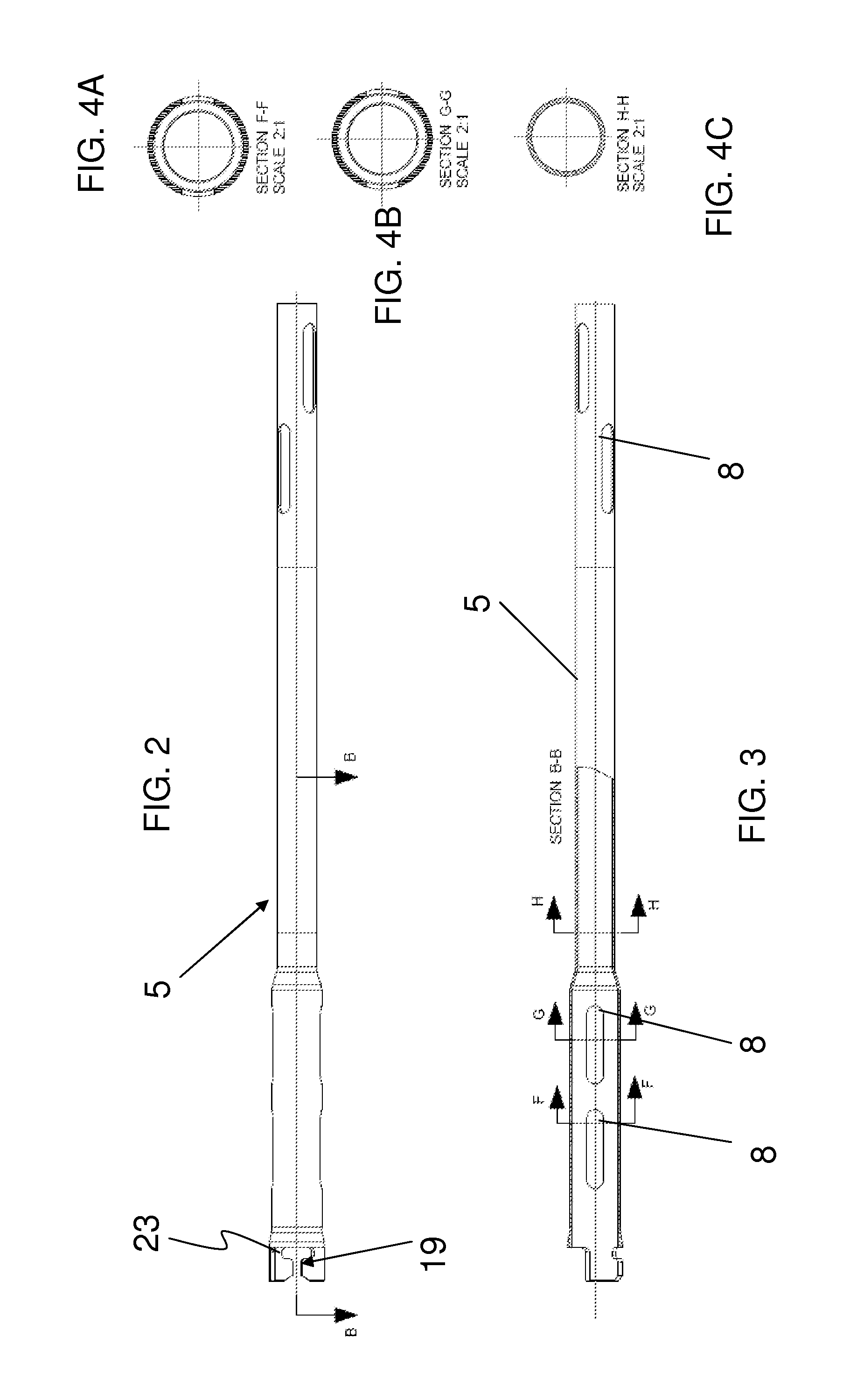
[0049]The nail 1 further comprises an outside tubular sleeve 5 hosting the rod 2 that is inserted coaxially into the tubular sleeve 5. Preferably, the nail 1 and its main components, the rod 2 and the sleeve 5 are cylindrical.

[0050]The rod 2 is cannulated, that is to say that it has an internal cavity extending for at least a portion along a longitudinal axis, indicated with X. The rod may be totally cannulated ...


PUM


Abstract

An intramedullary nail for a fractured elongated bone, comprising a cannulated rod having proximal and distal ends; an outside tubular sleeve for coaxially hosting and guiding the rod; and shape memory elements hosted in corresponding seats of the rod. Each shape memory element can be retractably housed in its respective seat in a first configuration, allowing insertion of the nail into the bone, and can project from a sleeve opening in another configuration. Proximal and distal pairs of the elements are provided at the proximal and distal rod ends. The proximal element pair lie on a same plane and are kept in their seats by a proximal cover. The distal element pair lie on an offset plane to the plane of the proximal element pair and are kept in their seats by a distal cover. This removes the need for bone screws to stabilize the nail inside the medullary canal.

Description

CROSS-REFERENCE TO RELATED APPLICATIONS[0001]The present application claims priority to European Patent Application No. 10197452.5, filed Dec. 31, 2010, the entirety of which is incorporated herein by reference.FIELD OF APPLICATION[0002]The present invention refers, in its most general aspect, to an Intramedullary nail suitable to be inserted into a fractured elongated bone, for example a femur or a tibia, and comprising a cannulated rod extending between a proximal end and a distal end.[0003]More particularly, the invention relates to a nail comprising:[0004]a cannulated rod extending between a proximal end and a distal end;[0005]an outside tubular sleeve for hosting said rod, the rod being coaxial with the sleeve and axially or angularly guided inside the tubular sleeve;[0006]shape memory elements hosted in corresponding seats of said rod; each elements being able to assume a configuration wherein is retractably housed in its respective seats, so to allow the insertion of the nail...

Claims


Application Information

Patent Timeline
Patent Type & Authority Patents(United States)
IPC IPC(8): A61B17/72
CPCA61B17/7258A61B2017/00867
Inventor COATI, MICHELEBAGNASCO, MARAROSSI, LUIGIMARINI, GRAZIANOROSSI, GRAZIANO
Owner ORTHOFIX SRL
Why Eureka
Try Eureka