Suture anchor implantation instrumentation system

a technology of instrumentation system and suture anchor, which is applied in the field of suture anchor implantation instrumentation system, can solve the problems of shoulder joint pain, shoulder joint instability, and shoulder injuries, and achieve the effects of convenient operation, reliable and repeatability

Active Publication Date: 2013-05-14
HOWMEDICA OSTEONICS CORP
View PDF283 Cites 38 Cited by
  • Summary
  • Abstract
  • Description
  • Claims
  • Application Information

AI Technical Summary

Benefits of technology

[0006]In yet another embodiment, the present invention may be a system for implanting an anchor into bone, the system comprising a cannulated guide comprising a proximal end, a distal end positionable proximate a bone, and a curved shaft extending between the proximal and distal ends; a drill comprising a proximal end configured to receive torque, a distal rotary drilling head, and a shaft extending between the proximal end and the rotary drilling head, wherein the shaft comprises a flexible portion and permits passage of the rotary drilling head through the shaft of the cannulated guide; and wherein one of the drill and the cannulated guide comprises a stop feature shaped to interface with the other of the drill and the cannulated guide to adjustably control a maximum range of motion of the rotary drilling head through the cannulated guide.
[0008]The curved labrum instrumentation of the present invention will make the existing SLAP and Bankart surgical procedures, in particular, the 5 and 6 o'clock position repairs, easier to perform by making it possible to achieve anchor hole vectors that are much closer to perpendicular with the surfaces of the scapular glenoid rim. This improved insertion vector will lessen the probability of anchor back out and thereby improve the quality of the surgical repair.
[0010]The handle portion of each guide may provide the user with a place to grasp the instrument during use and, in the case of using the drill, to provide a geometry that will prevent the user from drilling past a set drill depth. The guide handle is also cannulated to allow for the insertion of the flexible obturators, the flexible drill, and a flexible inserter for the suture anchor.
[0016]The surgical techniques employed during the use of the instrumentation of the present invention are similar to those already used for SLAP and Bankart surgical repairs. The curved geometry of this instrumentation makes these surgical procedures easier to perform and more reliable and repeatable. Initially, in a first embodiment, a cannula, such as a Stryker Corp. 8 mm DriLok™ cannula, or any suitable cannula known in the art, may be placed in the shoulder in a standard fashion. Then an appropriate flexible obturator is placed inside an appropriate curved guide and the curved guide is then inserted through the cannula and into the joint capsule. Alternatively, in another embodiment, the appropriate guide can be inserted percutaneously into the joint capsule, without the use of a cannula, and may be used with a trocar tip obturator, for example. Once the guide is in place, the obturator is removed from the curved guide. A flexible drill may then be inserted into the joint capsule via the guide. A proximal end of the flexible drill is connected to a standard orthopedic power drill and a pilot hole is drilled in the glenoid rim. The flexible drill is then removed from the guide. A flexible inserter may then be inserted into the joint capsule via the curved guide to insert a suture anchor previously placed thereon into the pilot hole such as a Stryker Corp. 3.5 mm TwinLoop™ suture anchor. The flexible inserter is then removed from the guide. The guide is then removed from the cannula and the cannula removed (or alternatively, the guide is withdrawn from the surrounding tissue if no cannula is used).

Problems solved by technology

Various shoulder injuries may result from dislocations, falling, throwing, or lifting.
These injuries result in pain and instability of the shoulder joints.

Method used


Image

  • Suture anchor implantation instrumentation system
  • Suture anchor implantation instrumentation system
  • Suture anchor implantation instrumentation system

Examples


Embodiment Construction

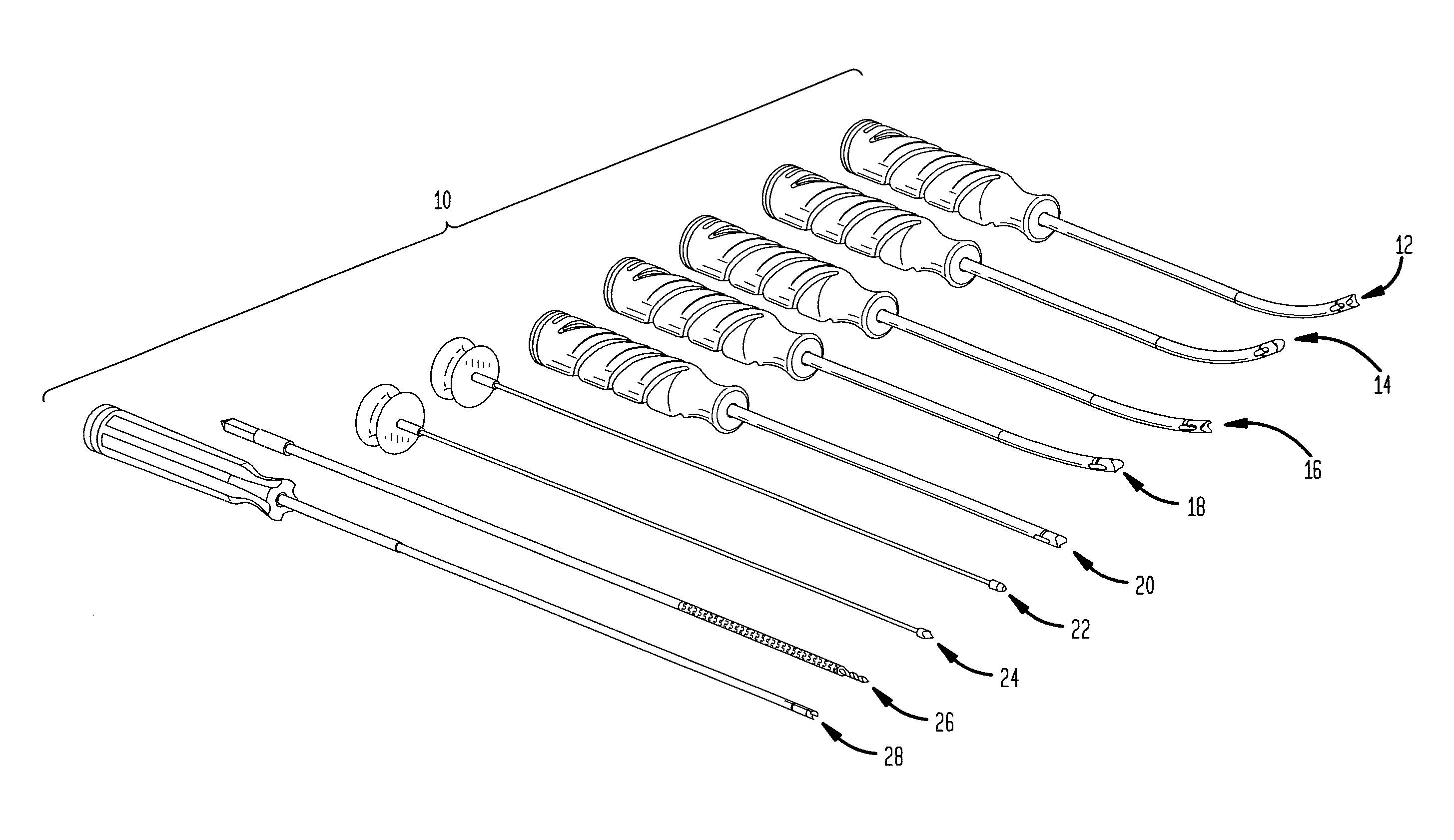
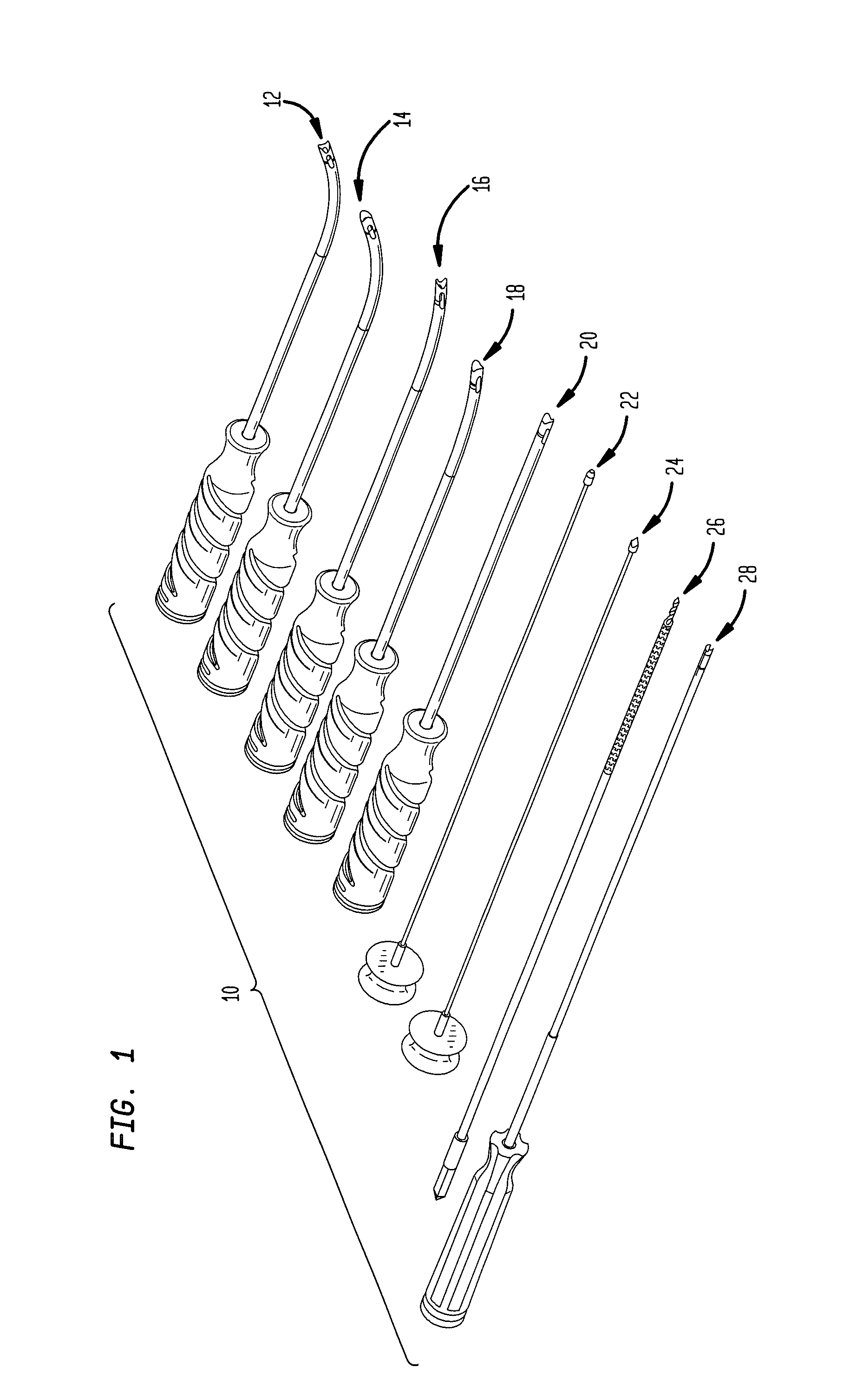
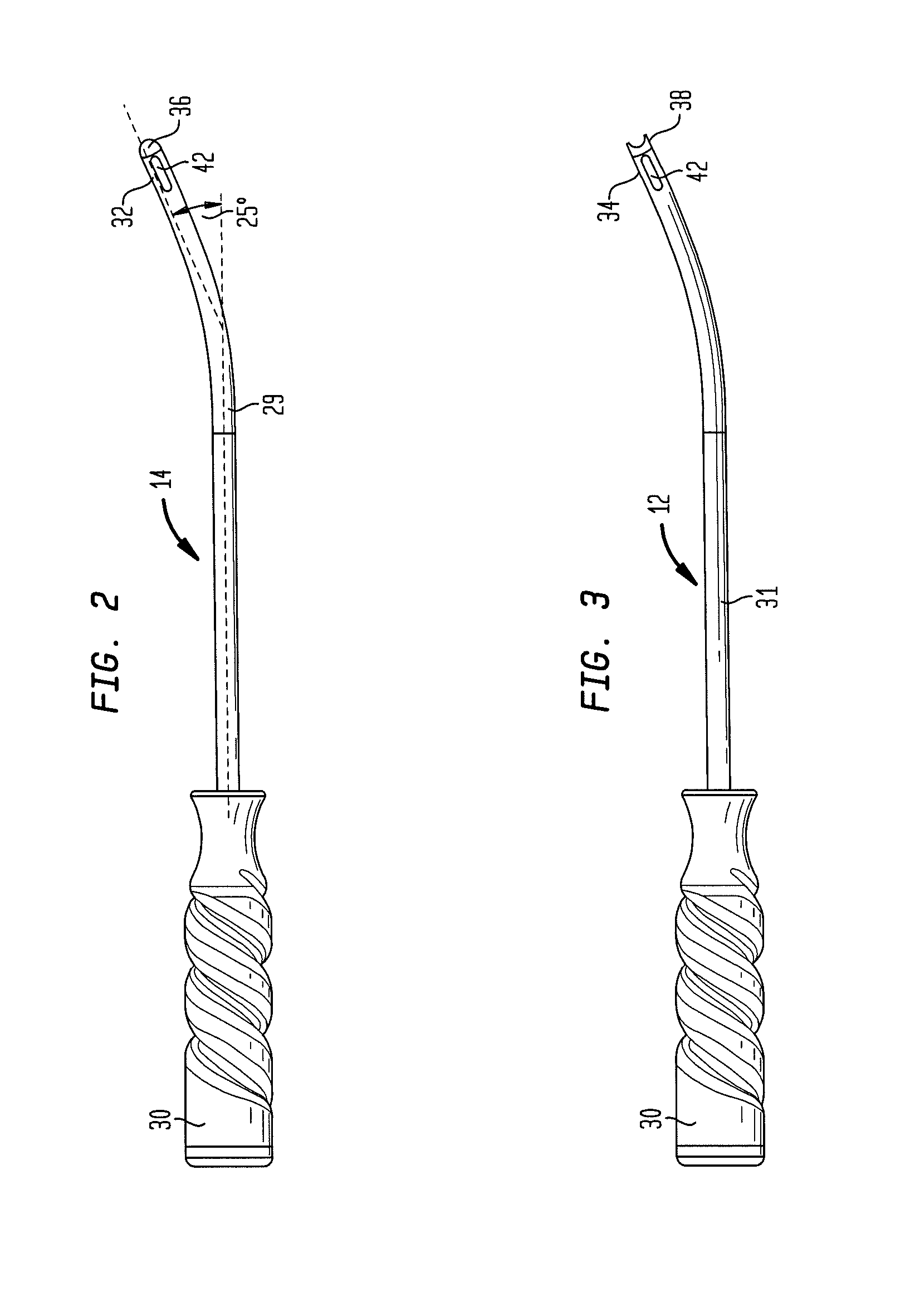
[0044]Referring to FIG. 1 there is shown one embodiment of an instrumentation system of the present invention generally denoted as 10. The system includes various curved guides having a curved guide shaft with a curved angle of between about 0° and about 90°. Specifically, the curved angle may be about 0° to about 25°, though any other angle is envisioned depending on the application of the guide. The system may consist of, for example, a 25° rotated orientation curved guide 12, a 25° standard orientation curved guide 14, a 12° rotated orientation curved guide 16, a 12° standard orientation curved guide 18, and a 0° (i.e. straight) guide 20. In one example, the rotated orientation guides may be used on the posterior glenoid rim, and the standard orientation guides may be used on the anterior glenoid rim, though this may be reversed if desired. Furthermore, in an alternate example, the rotated orientation guides may be used within the posterior portal, and the standard orientation gu...


PUM


Abstract

A system for implanting an anchor into bone, the system comprising a curved cannulated guide for percautaneous insertion, having a proximal end and a distal end; a flexible drill insertable through the curved guide from the proximal end to the distal end, the flexible drill having a shaft having a flexible portion; and a flexible inserter for inserting a suture anchor into a bore at the anatomical site formed by the flexible drill, the flexible inserter having a shaft having a flexible portion, wherein the flexible portions of both the flexible drill and flexible inserter include a series of discrete, interlocking segments.

Description

CROSS-REFERENCE TO RELATED APPLICATIONS[0001]This application is a continuation-in-part of U.S. application Ser. No. 12 / 460,310, filed on Jul. 16, 2009, the disclosure of which is incorporated herein by reference.BACKGROUND OF THE INVENTION[0002]Various shoulder injuries may result from dislocations, falling, throwing, or lifting. A common shoulder injury includes the separation of the glenoid labrum from the glenoid. For example, a Bankart lesion results from a labral tear that occurs in the anterioinferior region of the glenoid socket when the shoulder dislocates. A superior labral anterior posterior (SLAP) lesion typically occurs from throwing injuries, where the tear occurs at the superior region of the glenoid socket where the biceps tendon attaches to the shoulder. These injuries result in pain and instability of the shoulder joints.[0003]Arthroscopic stabilization for surgical treatment of shoulder instability has grown in popularity over the past decade. In particular, labra...

Claims


Application Information

Patent Timeline
Patent Type & Authority Patents(United States)
IPC IPC(8): A61B17/56
CPCA61B17/0401A61B17/1684A61B17/0469A61B2017/0441A61B2017/0409A61B17/17A61B17/1739A61B2017/320052
Inventor HOWARD, BRYAN PATRICKYEARSLEY, RYAN E.MILLER, M. TODDAUGE, II, WAYNE K.LEWIS, CHADJUSTIN, DANIEL F.SINNOTT, MARGARET MARY
Owner HOWMEDICA OSTEONICS CORP
Why Eureka
Try Eureka