
System for vibration confinement

a technology of vibration confinement and loudspeaker, which is applied in the field of loudspeakers, can solve the problems of loudspeaker that is fragile, lacks durability and reliability, and many problems, and achieves the effect of strengthening the interfa

Active Publication Date: 2013-05-14
APPLE INC
View PDF43 Cites 10 Cited by
  • Summary
  • Abstract
  • Description
  • Claims
  • Application Information

AI Technical Summary

Benefits of technology

This design effectively isolates the inner diaphragm from unwanted vibrations, reducing peak stress and peel loads, enhancing the robustness and manufacturing ease of the loudspeaker, resulting in improved frequency response and durability.

Problems solved by technology

However, numerous problems arise when the suspension member is attached to the diaphragm.
For example, the attachment of a suspension member with the diaphragm may permit spurious vibrations from the suspension system to be transmitted across the surface of the diaphragm, resulting in distortion and inaccuracies in the frequency response.
However, the loudspeakers associated with such approaches and designs can be difficult to manufacture, resulting in loudspeakers that are fragile and lacking in durability and reliability.

Method used


Image

  • System for vibration confinement
  • System for vibration confinement
  • System for vibration confinement

Examples


Embodiment Construction

[0025]Various aspects are now described with reference to the drawings. In the following description, for purposes of explanation, numerous specific details are set forth in order to provide a thorough understanding of one or more aspects. It may be evident, however, that the various aspects may be practiced without these specific details.

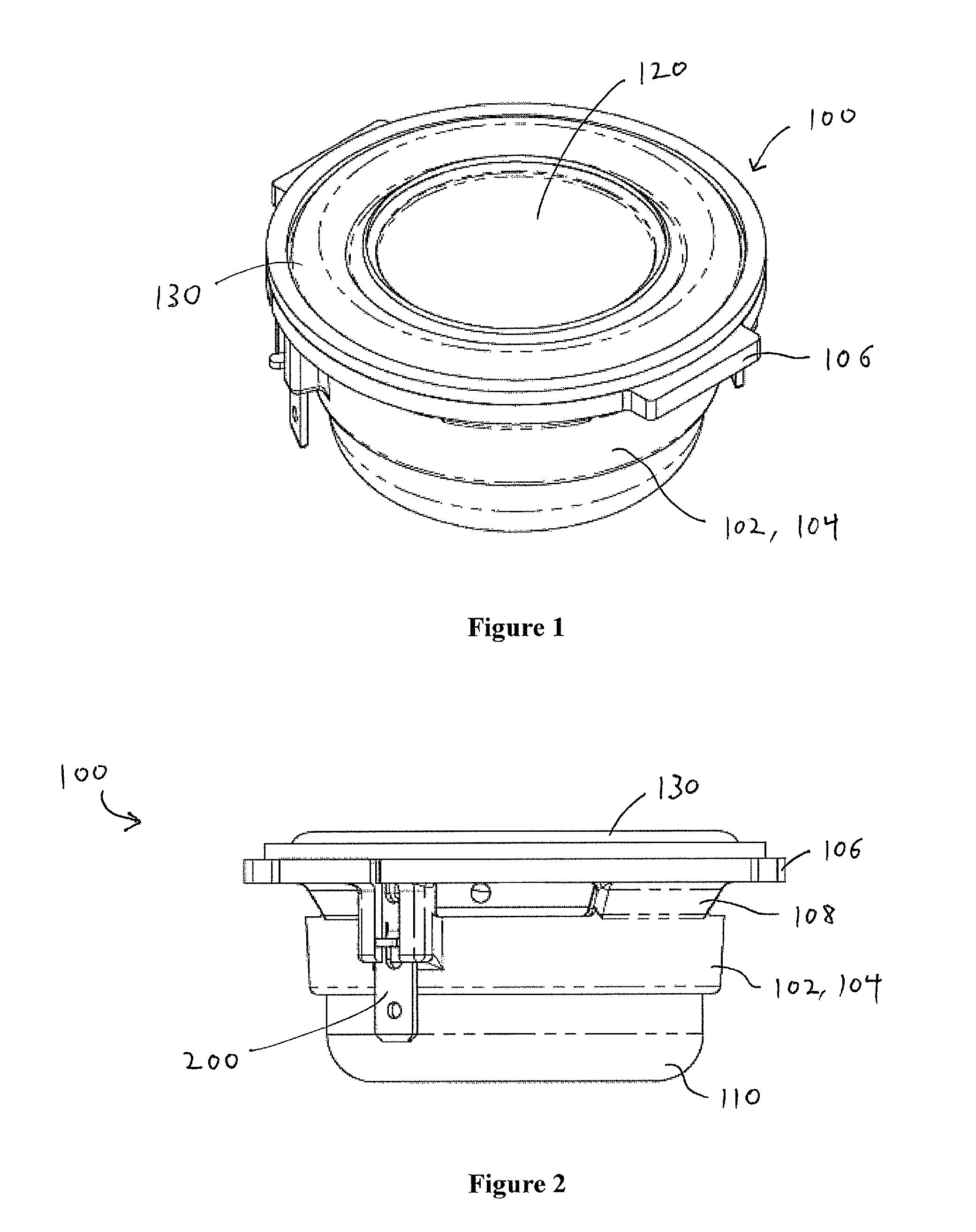
[0026]With reference to FIG. 1, there is provided an isometric view of a loudspeaker 100. The loudspeaker 100 may include a frame 102 that includes a circular perimeter 104 and a mounting ring 106 (e.g., an annular flat surface). The loudspeaker 100 may include a dome or diaphragm 120 within the frame 102. The loudspeaker 100 may include a suspension or surround system 130 positioned above the frame 102.

[0027]With reference to FIG. 2, there is provided a side view of the loudspeaker 100. The suspension system 130 extends upwardly from the mounting ring 106 of the frame 102. The frame 102 may further include a plurality of buttress blocks 108 and a ...


PUM


Abstract

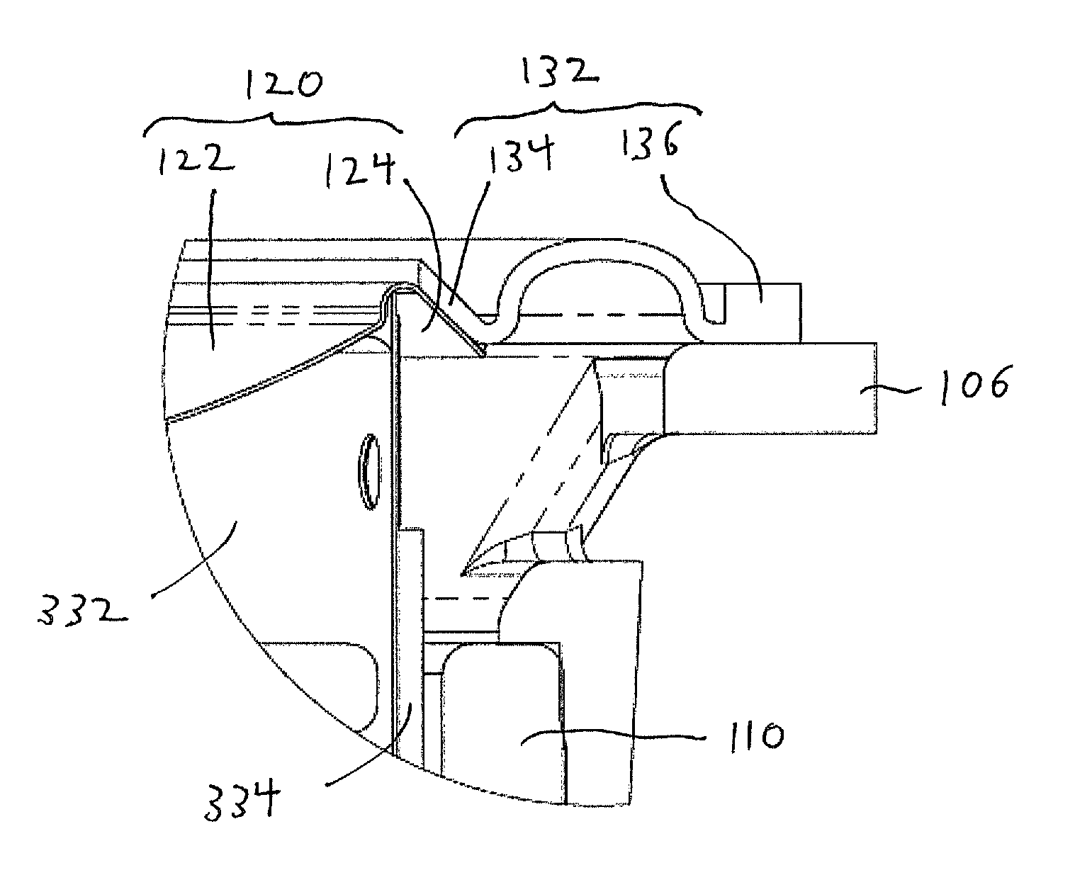
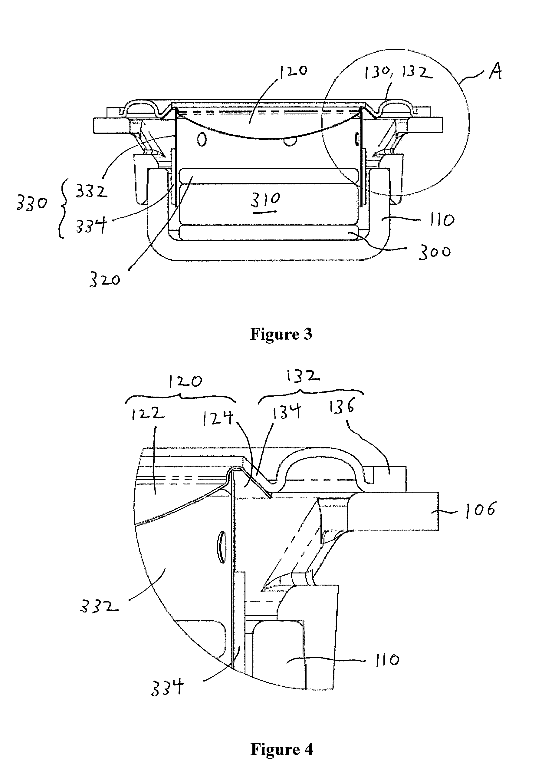
Systems and apparatuses are provided for vibration confinement and stress management in a loudspeaker. In one embodiment, the loudspeaker comprises a diaphragm that extends from an inner diaphragm region (e.g., dome or cone-shaped) to an outer diaphragm region, wherein the outer diaphragm region bends at a defined angle (e.g., between about 45 degrees and about 135 degrees) relative to the inner diaphragm region. The loudspeaker also comprises a suspension member extending from an inner suspension region to an outer suspension region, the inner suspension region overlapping and attaching with the outer diaphragm region. The bend in the diaphragm isolates the inner diaphragm region from spurious vibrations in the suspension member.

Description

BACKGROUND[0001]1. Field[0002]The present disclosure relates generally to the field of loudspeakers, and more particularly to the confinement of vibrations associated with a loudspeaker driver.[0003]2. Related Art[0004]There are numerous types of audio transducers or drivers for loudspeakers. A functionality of the driver is as a traditional direct radiator, which may include, for example, a moving voice coil immersed in a static magnetic field, coupled to a rigid diaphragm and a suspension system.[0005]A motor system of a loudspeaker may include a permanent magnet, surrounded by steel parts that direct and shape the magnetic field. The loudspeaker may also include a voice coil, which may be a conductive wire (e.g., copper clad aluminum), sometimes referred to as a voice coil wire, wrapped around a non-conductive bobbin, sometimes referred to as a voice coil former. The voice coil former can provide mechanical stability and a platform for transmitting the coil force to the diaphragm...

Claims


Application Information

Patent Timeline
Patent Type & Authority Patents(United States)
IPC IPC(8): H04R1/00
CPCH04R7/16H04R7/20H04R9/045H04R2207/021H04R7/24H04R9/06H04R31/003H04R2400/11
Inventor WILLIAMSON, CLAYTON
Owner APPLE INC
Learn More