Surgical manipulator

a technology of manipulators and manipulators, applied in the field of surgical manipulators, can solve the problems of large impact on the space and support staff of the operating room, the size, weight and volume of the most current system, and the majority of current systems do not provide haptic feedback

Active Publication Date: 2013-05-21
MACDONALD DETTWILER & ASSOC INC
View PDF152 Cites 86 Cited by
  • Summary
  • Abstract
  • Description
  • Claims
  • Application Information

AI Technical Summary

Problems solved by technology

The overall size, weight and volume of most current systems are a major issue in that they have a major detrimental impact on operating room facility space and the support staff who set-up the equipment.
The majority of current systems do not provide Haptic feedback.
Manual surgical tool exchange increases the surgical operating time; increasing the time the patient is required to remain under anaesthesia and increasing facility costs.
However, the drawback of conventional servomotors presently in use in many surgical robots is their long axial length, so a right-angle transmission means is needed if excessive lateral extension of the manipulator arm joints is to be avoided.
Of all the available right-angle transmission components at present, bevel gear pairs deliver high torque and backdrivability, but backlash is typically high and they seldom come in small packages.
The traditional standard bevel gear box has large backlash in transmission which is highly undesirable in applications where high precision is required in both directions of motion.
Worm gear boxes can have low-backlash configurations but its indirect proportional relationship between the efficiency versus the gear ratio leads to a bulkier and heavier overall unit, while also the lack of back-drivability is also undesirable in the event of crash recovery or calibration common to robotics applications.
Cable-pulley system provides an alternative to traditional gear-type mechanism, but introduces transmission error if any of the cable segments in the transmission chain is not tensioned properly.
None of the above mentioned inventions can be adapted to a single-actuator right-angle transmission application, and their means of cable tension adjustment all require extra room for additional elements which will lead to the increase in overall size of the transmission module.
Unfortunately, the mechanism does not allow for a right-angle drive version.
No commercially available right-angle transmission in the market currently has both zero-backlash and high efficiency capabilities in a compact in-line package.

Method used


Image

  • Surgical manipulator
  • Surgical manipulator
  • Surgical manipulator

Examples


embodiment 993

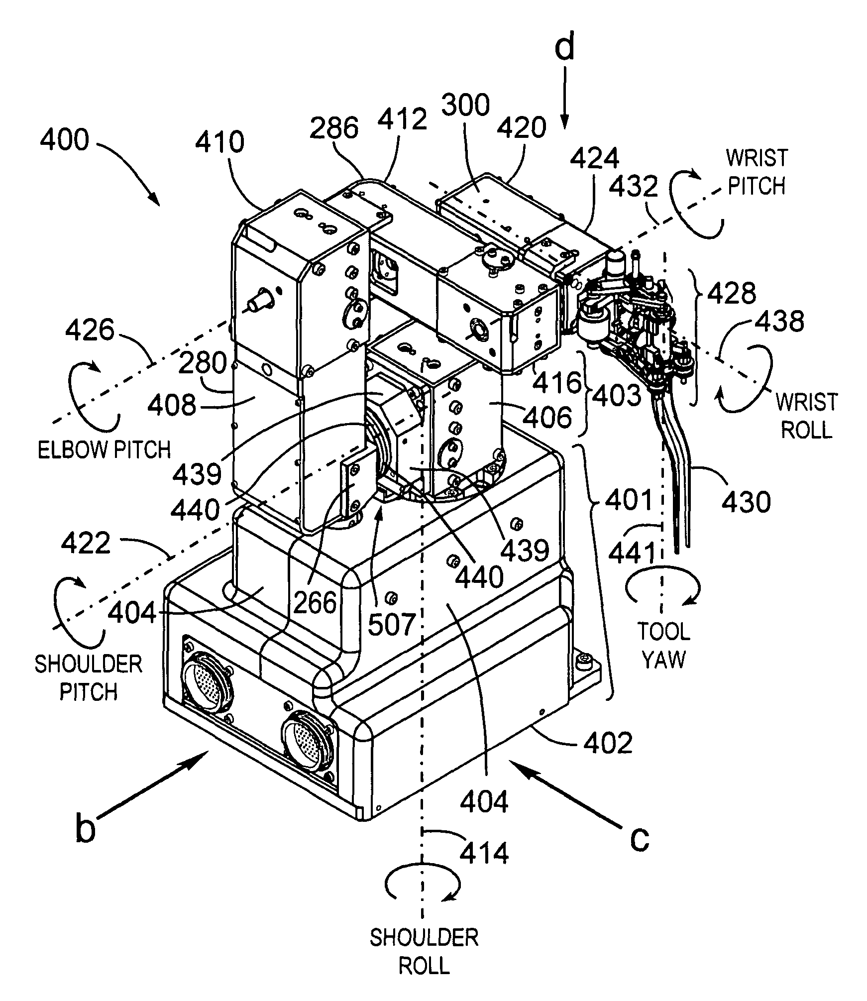
[0211]Referring to FIG. 21j, the modularity of the manipulator joints, in particular that at the wrist shaft 484 between the end-effector 428 and the wrist 420, can be used to attach various purpose-specific end-effectors to adapt to different target applications. In the embodiment with the default design of the manipulator 400 shown in FIG. 16a, all axes 414, 422, 426, 432 and 438 are included and are the same as described earlier. Using the modular quick-disconnect interface 850 described in the previous paragraph, end-effectors 428 with different functions can be attached to the arm to carry out different tasks. In the default embodiment 990, the end-effector 428 contains the tool-yaw joint 441 as the default design configuration. However, another embodiment 991 demonstrates an end-effector 428 without the sixth degree-of-freedom but instead just a straight instrument (such as a hand-drill). Embodiment 992 illustrates that another much smaller manipulator arm 881 can be attached ...

first embodiment

[0213]The end effecter 428 (FIG. 16a) connected to the end of the robotic wrist unit 424 holds a surgical tool 430 which can be detached from the end-effector 428 in a manner to be discussed after the discussion of the tools. FIGS. 22a to 22e show a surgical tool 430 which can be detachably mounted to end effecter 428 attached to the manipulator 400 (FIG. 16a). Referring to FIGS. 22c and 22d, tool 430 includes a main housing 500, a Teflon bushing 502 seated in the end of housing 500, a piston 504 sliding in housing 500 through Teflon bushing 502, a right hand forcep blade 506, a left hand forcep blade 508, and a forcep insert 510. The two forcep blades have a hole through them and a dowel 512 is inserted through the holes and the two blades pivot about this dowel 512 as the piston 504 moves in and out of main housing 500. Piston 504 includes a head portion 514 located at the outer end of the piston and a narrower neck 516 located between the head portion 514 and the rest of the body...


PUM


Abstract

The present invention provides a surgical manipulator including a manipulator arm, an end-effector held by the robotic arm, surgical tools held by the end-effector and manipulator joints, particularly right-angle drive devices for transmitting rotational motion in one axis to a perpendicular axis.

Description

CROSS REFERENCE TO RELATED U.S. PATENT APPLICATIONS[0001]This patent application relates to, and claims the priority benefit of U.S. Provisional Application Ser. No. 61 / 008,574 filed Dec. 21, 2007, and this application is a continuation-in-part (CIP) of U.S. utility patent application Ser. No. 11 / 812,094 filed on Jun. 14, 2007 entitled SURGICAL MANIPULATOR, filed in English, which are both incorporated herein in their entirety by reference.FIELD OF THE INVENTION[0002]The present invention relates to a surgical manipulator including a manipulator arm, an end-effector held by the manipulator arm, surgical tools held by the end-effector and manipulator joints, particularly right-angle drive devices for transmitting rotational motion in one axis to a perpendicular axis.BACKGROUND OF THE INVENTION[0003]The goal of surgical manipulator systems is to apply robotic and sensor technologies to improve the quality of patient surgical outcomes in a cost-effective manner. Surgical robotics can a...

Claims


Application Information

Patent Timeline
Patent Type & Authority Patents(United States)
IPC IPC(8): A61B17/00
CPCA61B19/2203B25J9/047B25J9/104A61B19/081A61B19/5212A61B2019/2223A61B2019/2234A61B2019/2242A61B2019/2246A61B2019/464A61B2034/715A61B34/71A61B90/361A61B46/10A61B2034/305A61B34/30A61B34/37A61B2090/064
Inventor YEUNG, BENNY HON BUNGREGORIS, DENNISBEDNARZ, BRONISLAWGRAY, MICHAEL A.
Owner MACDONALD DETTWILER & ASSOC INC
Why Eureka
Try Eureka