Broach handle with flexure spring

a flexure spring and handle technology, applied in the field of surgical tools, can solve the problems that no prior art discloses a simple design, and achieve the effect of preventing any separation

Active Publication Date: 2013-05-28
HOWMEDICA OSTEONICS CORP
View PDF14 Cites 9 Cited by
  • Summary
  • Abstract
  • Description
  • Claims
  • Application Information

AI Technical Summary

Benefits of technology

[0004]It is one aspect of the invention to provide an apparatus for holding a surgical broach during a broaching procedure. The apparatus may have a handle body having a handle bearing surface formed on one end of the body for acting on a complimentary bearing surface on the broach. An elastically deformable plate is mounted on the handle body in a manner which allows the plate to slide with respect to the body. The body may have a u-shape with an open side capable of receiving the plate. A plate is elastically deformable and has a catch element formed at a leading first end thereof adapted to engage a latch element formed on the broach. The elastically deformable plate has a spring section that may elongate elastically when applying a force between the broach and the handle body. An elongated loading member is pivotally rotatably connected to the handle body. The loading member has a cammed surface for engaging a cam follower surface on the elastically deformable plate and rotation of the cam moves a second end of the plate opposite the end with the catch element away from the broach contacting surfaces. This results in the catch element on the plate pulling on the latch element on the broach and preloading the broach against the handle broach contacting surface. This preloaded force is maintained during the broaching operation and is sufficient to prevent any separation between the broach and the broach handle during use.
[0005]When the broach or other tool is attached the elongated loading member has a first rotational position spaced from the handle body where the elastically deformable plate is in a relaxed state and has a second position, where rotated adjacent the handle body, where the elastically deformable plate is in a tensioned state. The tensioned state results from the movement of the second end of the elastically deformable plate away from the first plate end adjacent the broach handle body interface about the spring section of the plate. The cam surface on the elongated loading member includes a detent position adjacent the area of the cam surface which contacts the cam follower on the elastically deformable plate when in the fully tensioned state. The detent, which may be in the form of a protrusion from the cam surface, prevents the unintentional rotation of the loading member away from the handle body during use. Thus, the tension between the broach and the handle body is maintained.

Problems solved by technology

However, none of the prior art discloses a simple design which allows for the handle to be preloaded to the broach with a handle having a minimal number of parts and which handle allows for the simple and reliable cleaning thereof after use.

Method used


Image

  • Broach handle with flexure spring
  • Broach handle with flexure spring
  • Broach handle with flexure spring

Examples


Embodiment Construction

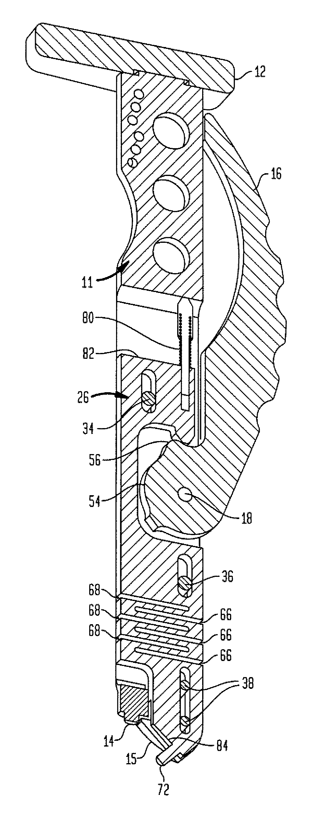
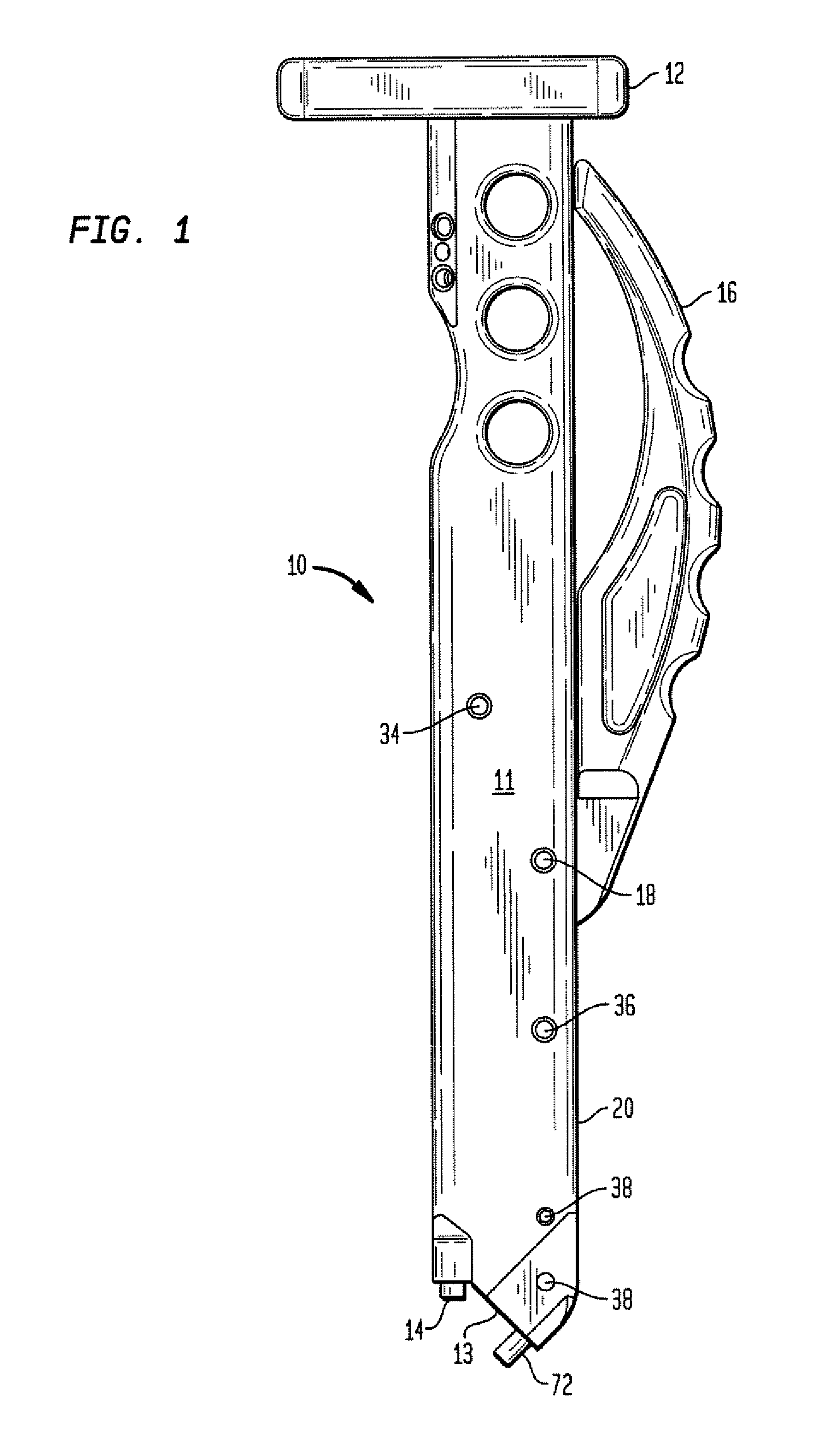
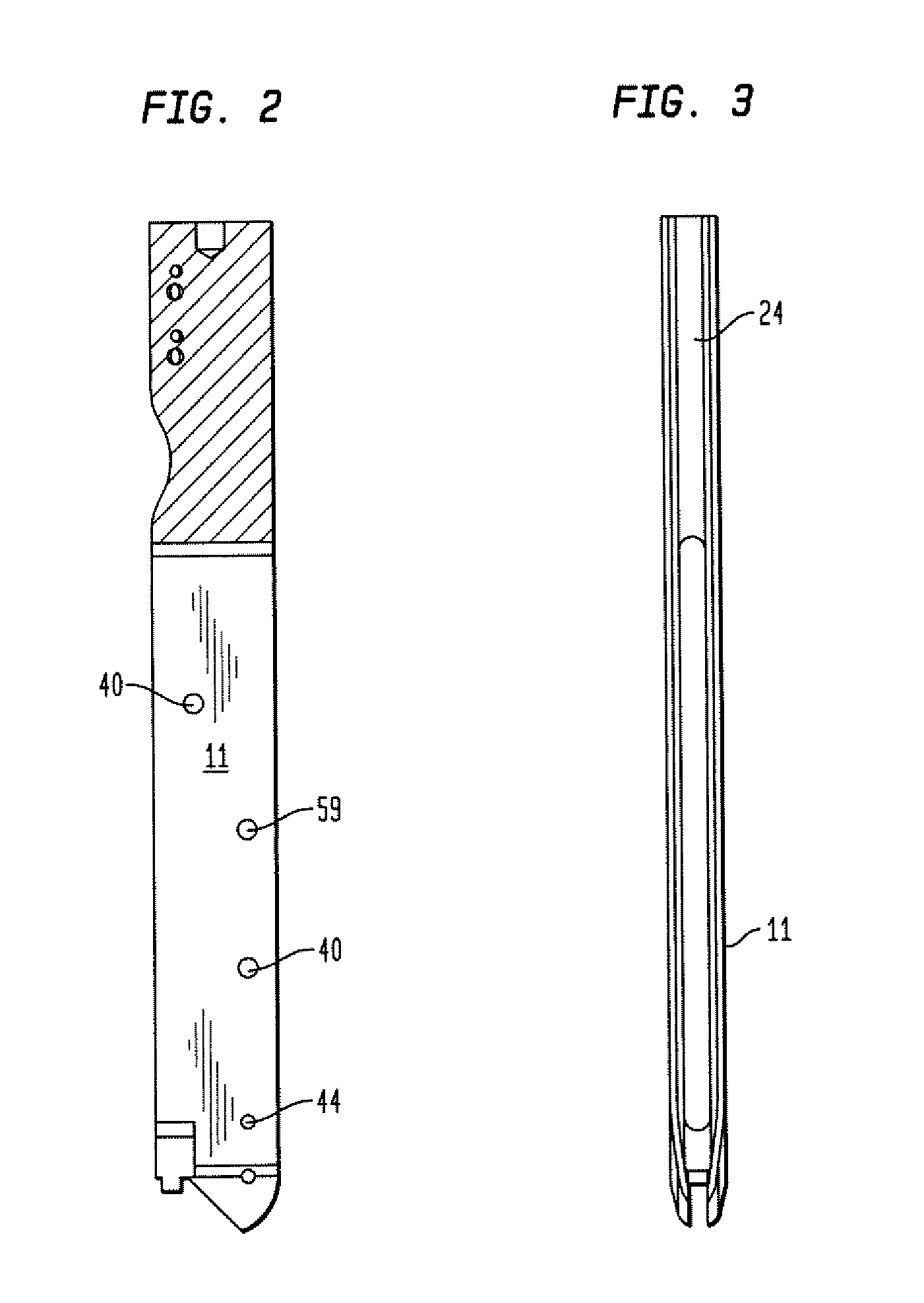
[0018]Referring to FIG. 1, there is shown a surgical tool generally denoted as 10 for engaging a surgical tool such as a rasp or broach. As indicated above, the handle could also engage a bone implant such as a humeral or femoral implant. Thus the following description applies equally to an implant or other device for insertion into an intramedullary canal. Surgical tool handle 10 has a handle body 11, including an impaction plate 12 at a second end thereof and a broach contact surface 13 at a leading first end and a broach contact extension element 14 extending from the first end thereof. Mounted within the hollow handle body 11 is a lever loading member 16 which is pivotally connected to body 11 by pivot pin 18. Loading member 16 is ergonomically designed to allow hand pivoting about pin 18 toward and away from a side 20 of the body. Referring to FIGS. 2 and 3, it can be seen that body 11 has a cavity 24 which forms a generally U-shaped tract for holding and guiding a deformable p...


PUM


Abstract

An instrument for holding a surgical tool or bone implant includes a handle with a bearing surface formed in one end for engaging the surgical tool. An elastically deformable plate is mounted on the handle body the plate having a catch element formed on a leading end thereof adapted to engage a coupling element formed on the surgical tool. The elastically deformable plate includes a cam follower formed in a recess thereon and includes a deformable spring section intermediate the can elements and the plate end with the catch element. An elongated pivotable loading member is rotatably mounted on the handle body. The loading member includes a cam surface for engaging the cam follower surface on the deformable plate. The cam surface on the loading member is shaped to elastically deform the elastically deformable plate section in a direction away from the plate catch element to thereby load and maintain a connecting force between the plate and the surgical tool or bone implant.

Description

BACKGROUND OF THE INVENTION[0001]This invention relates to a surgical tool for engaging a rasp or broach during a surgical procedure. More particularly, the invention relates to a handle that can selectively releasably hold a surgical instrument such as a broach or rasp during the preparation of a bone canal.[0002]Implantations of prosthetic implants such as femoral components or humeral components require forming a shaped cavity in the proximal femur or humerus. Often as part of this procedure a broaching or rasping operation is performed utilizing a broach or rasp having the shape of the femoral prosthetic component or humeral prosthetic component to produce a matching cavity or a cavity slightly larger when using bone cement. Broach holding tools or instruments have been provided to releasably engage multiple different size broaches or rasps. These holding instruments have various methods of locking the broach or rasp to the handle.[0003]Typical broach handles are shown, for exam...

Claims


Application Information

Patent Timeline
Patent Type & Authority Patents(United States)
IPC IPC(8): A61F2/46
CPCA61B17/1604A61B17/1668A61B17/1684A61B2017/00464
Inventor NELSON, ANDREWMCGOVERN, MICHAEL A.SPLIETH, ROYBARILE, GENNARO A.
Owner HOWMEDICA OSTEONICS CORP
Why Eureka
Try Eureka