
Pipe for the air intake circuit of a motor vehicle engine, and circuit incorporating the same

a technology for air intake circuits and motor vehicles, which is applied in the direction of machines/engines, combustion air/fuel air treatment, etc., can solve the problems of high pipe manufacturing cost and penalizing the overall manufacturing cost of m-aramid, and achieve heat resistance and mechanical strength that is also satisfactory.

Active Publication Date: 2013-05-28
HUTCHINSON SA
View PDF24 Cites 6 Cited by
  • Summary
  • Abstract
  • Description
  • Claims
  • Application Information

AI Technical Summary

Benefits of technology

The invention is a pipe made of PET that has improved resistance to high temperatures. It uses a special type of crosslinking agent, called an ACM, which is crosslinked with a non-amino system that is compatible with PET. This helps to prevent the pipe from melting when exposed to high temperatures. The pipe also has good mechanical strength and can withstand high levels of pressure. The ACMs used in the pipe are widely available and cost-effective. The pipe has an inner layer made of an ACM crosslinked with an amine, which further improves its heat resistance. Overall, this invention provides a cost-effective solution for manufacturing pipes that can withstand high temperatures.

Problems solved by technology

However, m-aramid has the drawback of penalizing the overall manufacturing cost of the pipe when compared with PET (polyethylene terephthalate) especially, which is a much less expensive material.
A major drawback of the pipe presented in that document lies in the choice of this complex and expensive crosslinking system in relation with the ACM or AEM elastomer bearing sites that are necessarily carboxyls, and in the resulting relatively high manufacturing cost for the pipe.

Method used


Image

  • Pipe for the air intake circuit of a motor vehicle engine, and circuit incorporating the same
  • Pipe for the air intake circuit of a motor vehicle engine, and circuit incorporating the same

Examples


Embodiment Construction

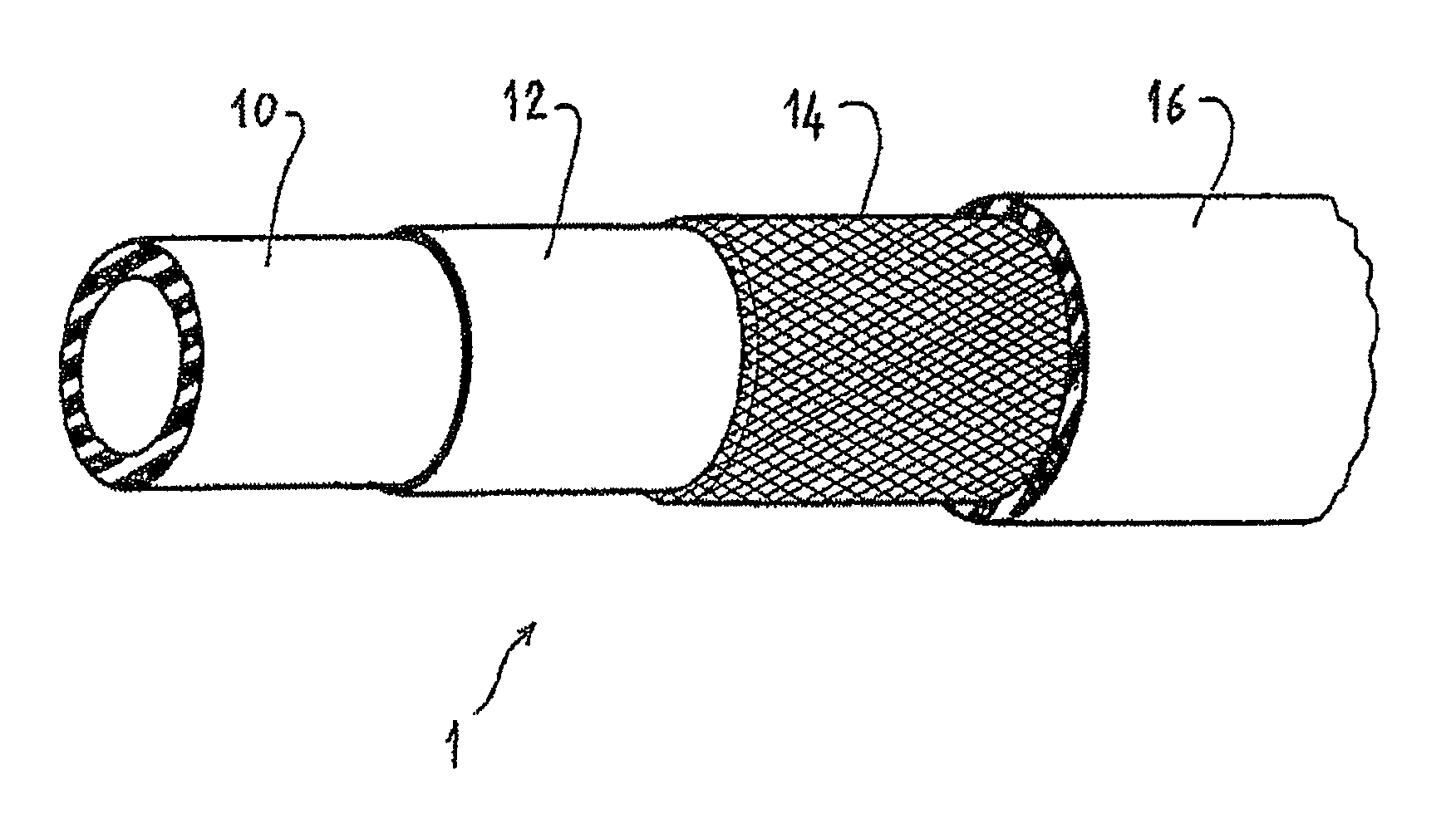
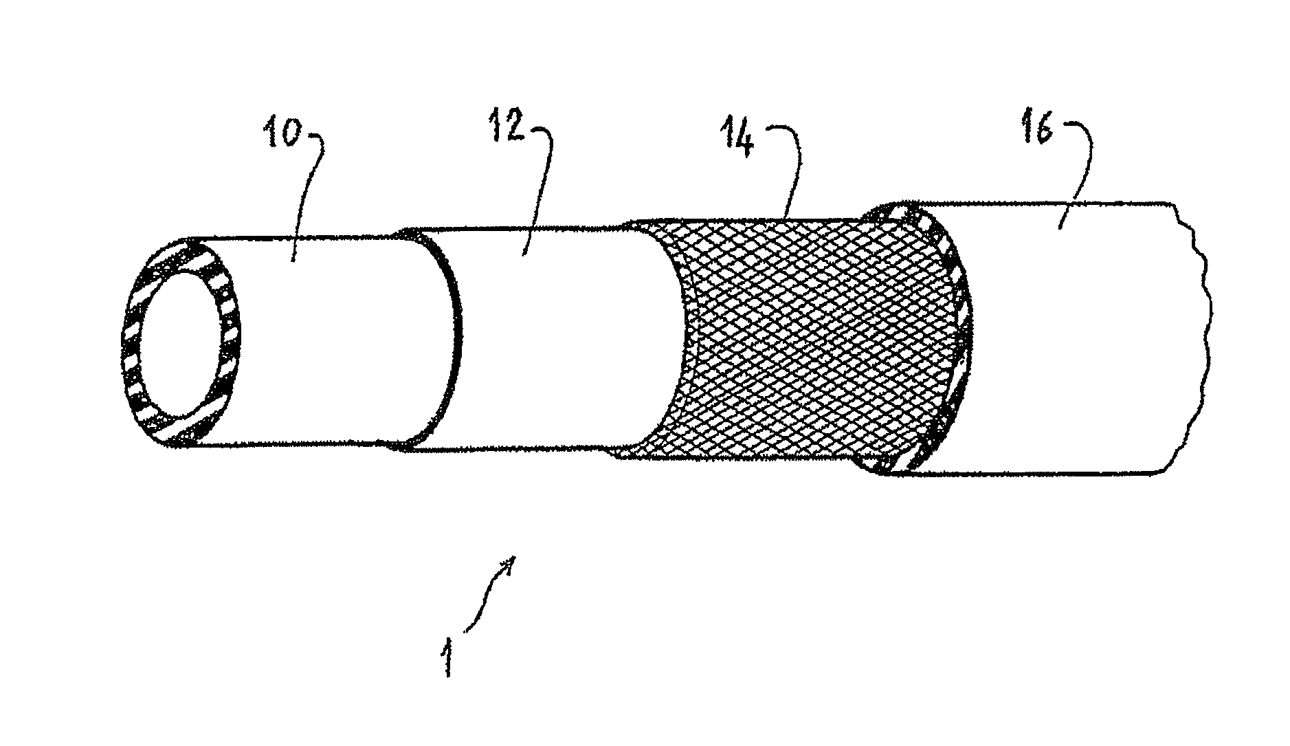
[0028]The pipe 1 illustrated in this FIGURE comprises, radially from the inside outward:

[0029]an elastomeric inner layer 10 that is leaktight and resistant to the corrosiveness of the transported fluid, i.e. especially designed to withstand the temperature of the air-oil mixture of an air intake circuit at the outlet of a turbocompressor and the corrosiveness of the oil contained in this mixture, the layer 10 possibly having a thickness of about 1.5 mm and being based, for example, on at least one ACM crosslinked with an amine,

[0030]an elastomeric intermediate layer 12 provided to facilitate the adhesion between the layer 10 and an outer layer 16 of the pipe, the layer 12 possibly having a thickness of about 0.5 mm and being based, for example, on at least one ACM crosslinked with sulfur,

[0031]a reinforcing structure 14, such as ribbed fabric whose yarns are made at least partly of PET (it being pointed out that this structure 14 may also incorporate yarns of different stiffness, fo...


PUM

PropertyMeasurementUnit
temperatureaaaaaaaaaa
pressureaaaaaaaaaa
temperatureaaaaaaaaaa

Abstract

The present invention relates to a pipe usable for an air intake circuit of a motor vehicle engine, and to this air intake circuit in particular for the intake of air at the outlet of a turbocompressor that comprises at least one such pipe.This pipe (1) comprises at least one inner elastomer layer (10), one outer elastomer layer (16), one intermediate elastomer layer (12) and one reinforcing structure (14) which is situated between the intermediate and outer layers and which comprises yarns based on an aliphatic polyester, such as a PET, each intermediate and outer layer being formed from a composition based on at least one acrylate copolymer (ACM).According to the invention, said composition is crosslinked by means of a system chosen from the group consisting of those based on at least one soap combined with sulfur, with a urea derivative and those based on a thiadiazole.

Description

FIELD OF THE INVENTION[0001]The present invention relates to a pipe usable for an air intake circuit of a motor vehicle engine, and to this air intake circuit in particular for the intake of air leaving a turbocompressor that incorporates at least one such pipe. The invention applies more generally to a fluid transportation pipe, irrespective of the nature of this fluid and of its circulation conditions.BACKGROUND[0002]In general, a pipe that transports a fluid in liquid or gaseous form must especially withstand the pressure, temperature and corrosiveness of the transported fluid, on the one hand, and the corrosiveness of the surrounding medium, on the other hand.[0003]In the case of an air intake pipe for a turbocompressed motor vehicle engine, the fluid is hot air at a pressure of about 1.5 to 2 bar and at a temperature of about 100° C. to 200° C., and this hot air is charged with oil (in particular oil used to lubricate the turbocompressor), which makes it necessary to ensure tha...

Claims


Application Information

Patent Timeline
Patent Type & Authority Patents(United States)
IPC IPC(8): B29D22/00
CPCB32B1/08B32B25/14C08L31/04F16L11/085F02M35/10321F02M35/10334C08L33/08Y10T428/1393B32B5/026B32B25/08B32B27/308B32B2262/0261B32B2262/0276B32B2307/306B32B2307/50B32B2307/732
Inventor NICOLAS, LUDOVICBIERCE-ARGY, GWENAELLEHOUEE, SANDRINELARROQUE, CHRISTIANCALISKAN, ALPER
Owner HUTCHINSON SA
Learn More