
Image supporting material, method for use thereof and image forming apparatus utilizing the same

a technology of image supporting material and image forming apparatus, which is applied in the field of image supporting material, can solve the problems of inability to obtain satisfactory image quality, low temperature fixing property, heat resistance and mechanical strength at the same time, and achieve the effects of improving image fixing property, regulating viscosity characteristics, and uniform luster

Active Publication Date: 2007-09-11
FUJIFILM BUSINESS INNOVATION CORP
View PDF10 Cites 2 Cited by
  • Summary
  • Abstract
  • Description
  • Claims
  • Application Information

AI Technical Summary

Benefits of technology

The solution provides a high-luster, uniform image with improved heat resistance, mechanical strength, and low-temperature fixing properties, enabling efficient energy consumption in the fixing process while preventing image defects like blocking.

Problems solved by technology

In such image forming apparatus, in case of adopting the image supporting material with the aforementioned thermoplastic resin layer as a base material, a white PET film or a coated paper results in an extremely expensive image supporting material though the image quality can be improved.
On the other hand, an inexpensive plain paper is associated with a technical drawback of being unable to obtain a satisfactory image quality.
Also in case the aforementioned thermoplastic resin is principally formed by an amorphous resin such as polyester, polystyrene or polyacrylic resin, there is encountered a technical drawback that a low-temperature fixing property, a heat resistance and a mechanical strength cannot be satisfied at the same time.
On the other hand, an image of a smooth surface as in a photograph may cause a blocking phenomenon (surfaces being stuck unseparably or damaged even when separated) when let to stand in a state where the front surface of the image is in contact with the front surface or the rear surface of another image, or with a material of an album, in a high temperature environment such as a storage in an automobile or in a warehouse in summer or a transportation in a ship bottom.
Thus the measures for improving mechanical strength and the heat resistance are contradictory to those for improving the low-temperature fixing property.
Also it is necessary to employ a higher fixing temperature particularly in case of preparing an image of a high gloss as in a silver halide-based photograph, so that it becomes further difficult to meet the three requirements at the same time.
Also in comparison with a silver halide-based photograph, such image supporting material is inferior in luster and whiteness, and cannot provide a satisfactory photographic quality by forming a color toner image thereon.
In this case, however, there is encountered a technical drawback that a preferred surface structure of a high gloss uniform over the entire image cannot be obtained because the light diffusion layer at the surface of the image supporting layer has a high melt viscosity at the fixing step.

Method used


Image

  • Image supporting material, method for use thereof and image forming apparatus utilizing the same
  • Image supporting material, method for use thereof and image forming apparatus utilizing the same
  • Image supporting material, method for use thereof and image forming apparatus utilizing the same

Examples


embodiment 1

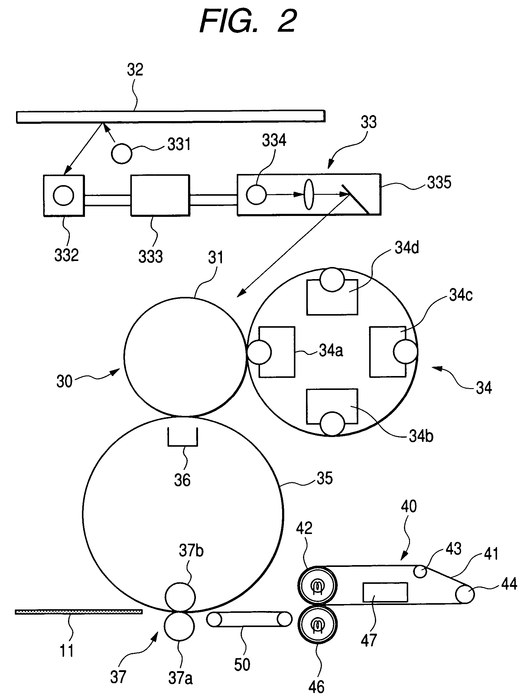
[0077]FIG. 2 shows an embodiment 1 of a color image forming apparatus embodying the present invention.

[0078]An image forming apparatus of the present embodiment shown in FIG. 2 is provided with an image forming unit 30 for forming, on an image supporting material 11, a color toner image 12 (cf. FIG. 6) formed for example by yellow, magenta, cyan and black color components, a fixing apparatus 40 for fixing the color toner image 12 formed by the image forming unit 30 on the image supporting material 11, and a conveying apparatus 50 for conveying the image supporting material 11 to the fixing apparatus 40.

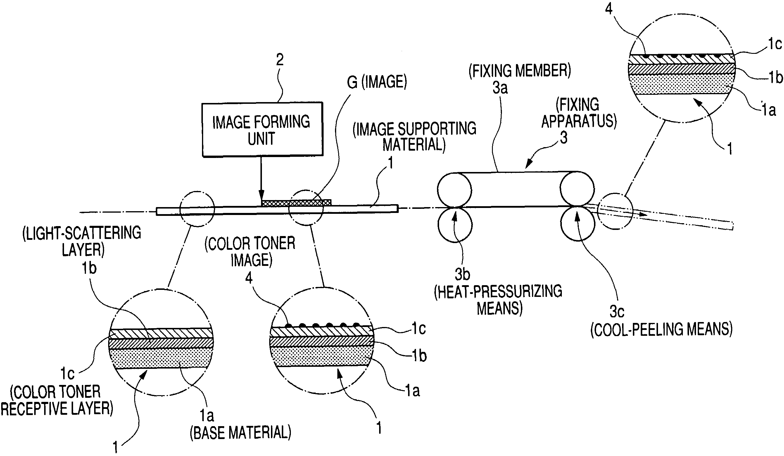
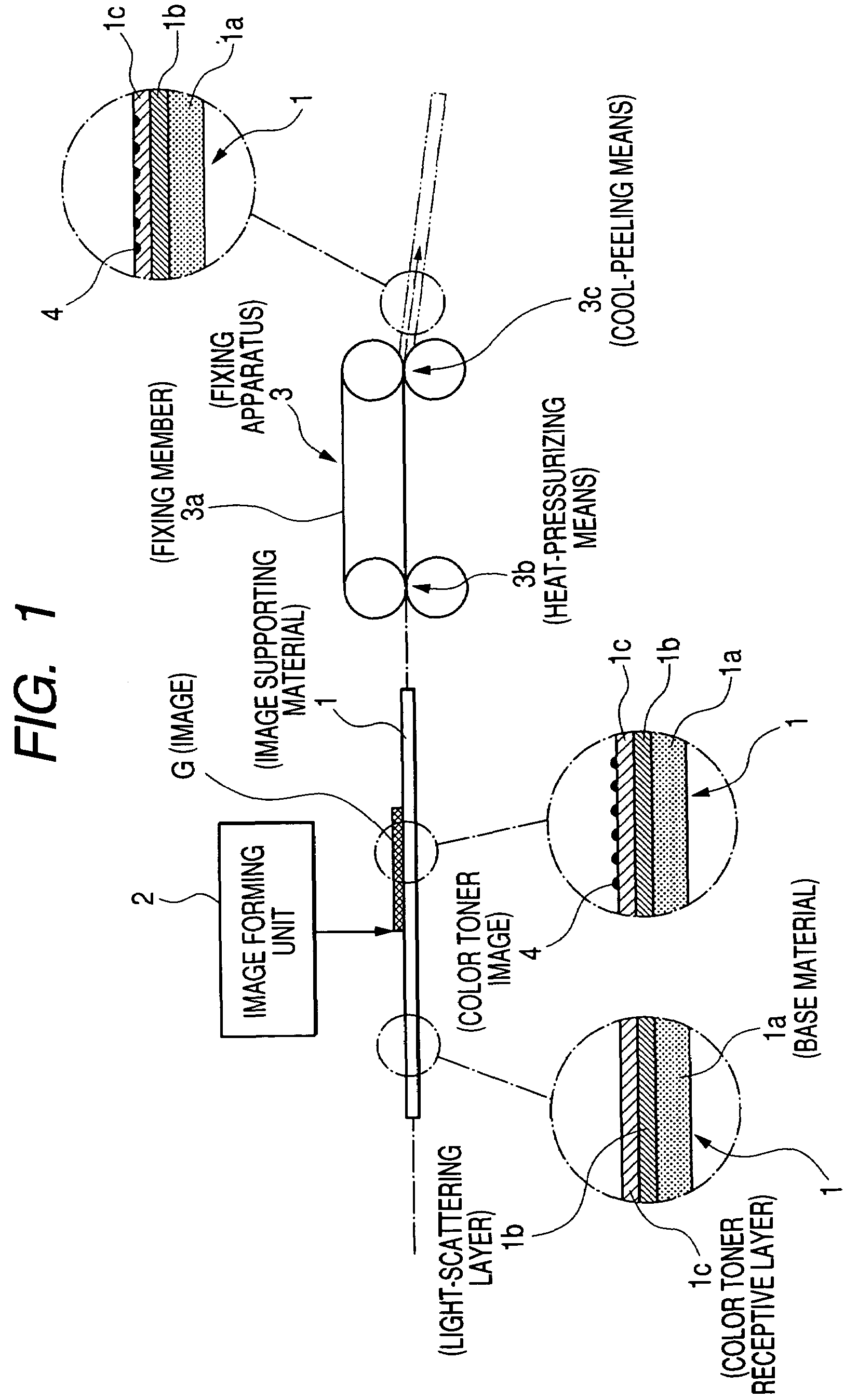
[0079]In the present embodiment, the image supporting material 11 at least includes, as shown in FIG. 3A on a base paper 11a of a basis weight of 100 to 250 gsm, a light scattering layer 11b of a thickness of 20 to 50 μm containing a white pigment in an amount of 20 to 40 wt. %, and thereon a color toner receptive layer 11c of a thickness of 5 to 20 μm containing at least a thermoplas...

example 1

Color Image Forming Apparatus

[0335]As the image forming apparatus, there was employed the image forming apparatus shown in FIG. 2. An image forming process speed was 160 mm / sec except for the fixing process. A weight ratio of the toner and the carrier, a charging potential of the photosensitive member, an exposure amount and a developing bias were so regulated as to obtain a development amount of the color toner of 0.5 mg / cm2 in a solid image area.

Color Toner Developer

[0336]The color toner developer X was employed.

Image Supporting Material

Base Paper

[0337]A base of a thickness of 150 μm formed with pulps was employed.

Light Scattering Layer

[0338]One hundred parts by weight of polyethylene resin were mixed with 25 parts by weight of titanium dioxide (KA-10, particle size: 300-500 nm, manufactured by Titan Kogyo Co.), charged in a melt extruder heated at 200° C., discharged from a T-die and laminated to a flame treated surface of the base paper by nipping between a nip roller and a cool...

example 2

[0356]A color image was prepared in the same manner as in Example 1, except that the color toner receptive layer was changed in the following manner.

Color Toner Receptive Layer

[0357]40 parts by weight of the crystalline polyester resin B and 60 parts by weight of the amorphous polyester resin I were subjected to a melt-mixing for 10 minutes in an extrusion kneader heated at 240° C., and pellets prepared therefrom were charged in a melt extruder heated at 170° C., discharged from a T-die and laminated to the base paper, bearing the light scattering layer, by nipping between a nip roller and a cooling roller to obtain a color toner receptive layer of a thickness of 20 μm. In the melt-mixing of the resins, T0=230° C. at t0=5 minutes. The color toner receptive layer had T1 of 78° C.


PUM

PropertyMeasurementUnit
temperature Tbaaaaaaaaaa
viscosityaaaaaaaaaa
temperature T1aaaaaaaaaa

Abstract

The present invention provides an image supporting material for fixably supporting a color toner image, the material including a base material, a light scattering layer provided on the base material and containing a white pigment and a thermoplastic resin, and a color toner receptive layer provided on the light scattering layer and containing at least a thermoplastic resin, wherein the thermoplastic resin in the light scattering layer is constituted of a polyolefin or a polyolefinic copolymer having a temperature, at which viscosity becomes 5×10³ Pa·s, of 100° C. or higher, and the thermoplastic resin in the color toner receptive layer is constituted of a resin obtained by melt mixing of a crystalline polyester resin and an amorphous resin and having a temperature, at which viscosity becomes 103 Pa·s, equal to or higher than 65° C. but lower than 80° C.

Description

BACKGROUND OF THE INVENTION[0001]1. Field of the Invention[0002]The present invention relates to an image supporting material for use in an image forming apparatus such as a copying machine or a printer, and more particularly to an image supporting material adapted for use in color image formation for example by an electrophotographic process, a method for use thereof and an improvement in an image forming apparatus utilizing the same.[0003]2. Background Art[0004]For a color image formation in a prior color image forming apparatus for example by an electrophotographig process, following image forming steps are usually adopted.[0005]A light reflected from an illuminated original is color separated by a color scanner and subjected to image processing and color correction in an image processing apparatus to obtain image signals of plural colors, each of which is converted into a modulated laser beam for example with a semiconductor laser. An image bearing member, utilizing an inorganic...

Claims


Application Information

Patent Timeline
Patent Type & Authority Patents(United States)
IPC IPC(8): B32B27/08B32B27/10B32B27/32B32B27/36G03G7/00B32B27/18G03G5/02G03G15/00G03G15/20
CPCB32B27/18B32B27/36B32B27/32Y10T428/263Y10T428/24901Y10T428/27Y10T428/24975Y10T428/25Y10T428/24934Y10T428/24967Y10T428/265Y10T428/264Y10T428/2495Y10T428/26Y10T428/24959Y10T428/24893Y10T428/24942Y10T428/24802Y10T428/31786Y10T428/3179Y10T428/31797G03G5/02G03G7/00B32B27/08B32B27/20B32B2307/704B32B2307/75
Inventor IDE, OSAMUHAYASHI, SHIGERUDAIMON, KATSUMI
Owner FUJIFILM BUSINESS INNOVATION CORP
Learn More