Anti-theft marking for copper clad steel

a technology of copper clad steel and anti-theft marking, which is applied in the direction of insulated conductors, power cables, cables, etc., can solve the problems of more potential damages and dangers, increased damage, and possible outages

Active Publication Date: 2013-05-28
BISON PATENT LICENSING LLC
View PDF12 Cites 7 Cited by
  • Summary
  • Abstract
  • Description
  • Claims
  • Application Information

AI Technical Summary

Problems solved by technology

However, once the wire is cut the damage has been done to the utility system, outages may have occurred, technicians will need to respond to the scene, and danger to humans may have been created, especially if the cut wire was a grounding wire.
Also, the thief might cut other wires just to see if other wires are pure copper wires or the CCS wires, which creates more potential damages and dangers.
Moreover, it is intended that thieves will come to learn that the new wire's appearance signifies a CCS wire, which is not valuable as recyclable material and hence would not justify their efforts and / or their exposure to the risk of being caught.

Method used


Image

  • Anti-theft marking for copper clad steel
  • Anti-theft marking for copper clad steel
  • Anti-theft marking for copper clad steel

Examples


first embodiment

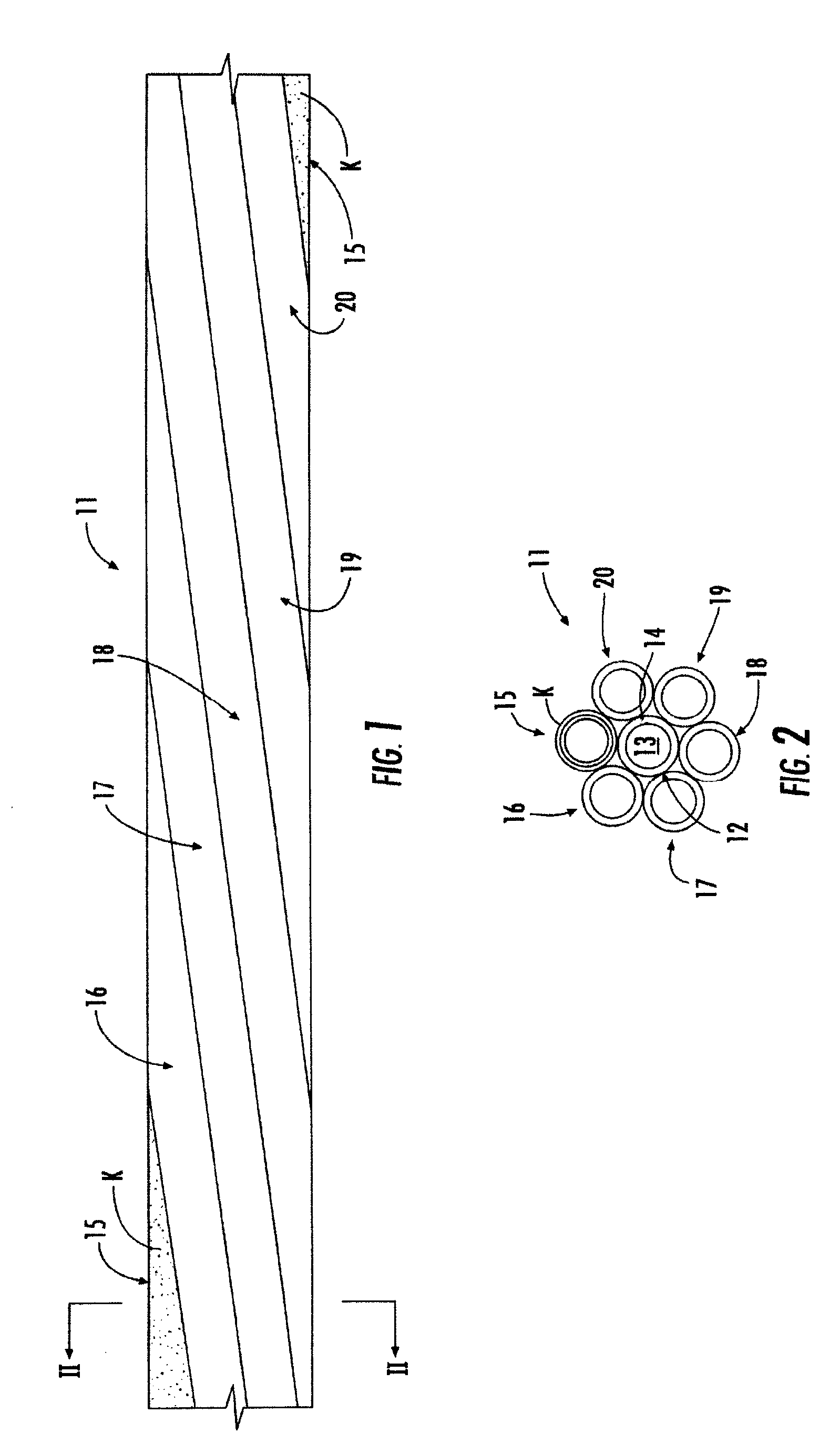
[0040]FIGS. 1 and 2 show a wire 11, such as a grounding wire, in accordance with a The wire 11 includes a center wire 12. In one instance, the center wire 12 has a steel core 13 and a copper clad layer 14 surrounding the steel core 13. However, in other instances (such as FIGS. 7 and 8), the center wire 12 could be an all steel wire.

[0041]A plurality of outer copper clad steel wires 15, 16, 17, 18, 19 and 20 are twisted around the center wire 12. The outer copper clad steel wires 15, 16, 17, 18, 19 and 20 also have a steel core surrounded by a cladding layer in the embodiments of the present invention. Although the illustrated embodiment shows six outer CCS wires 15, 16, 17, 18, 19 and 20 around one center wire 12, other configurations could be made, such as eight around one, nine around one, ten around three, etc.

[0042]An outer coating K is formed over at least one of the plurality of outer copper clad steel wires 15, 16, 17, 18, 19 and 20. For example, in FIGS. 1 and 2, the coati...

second embodiment

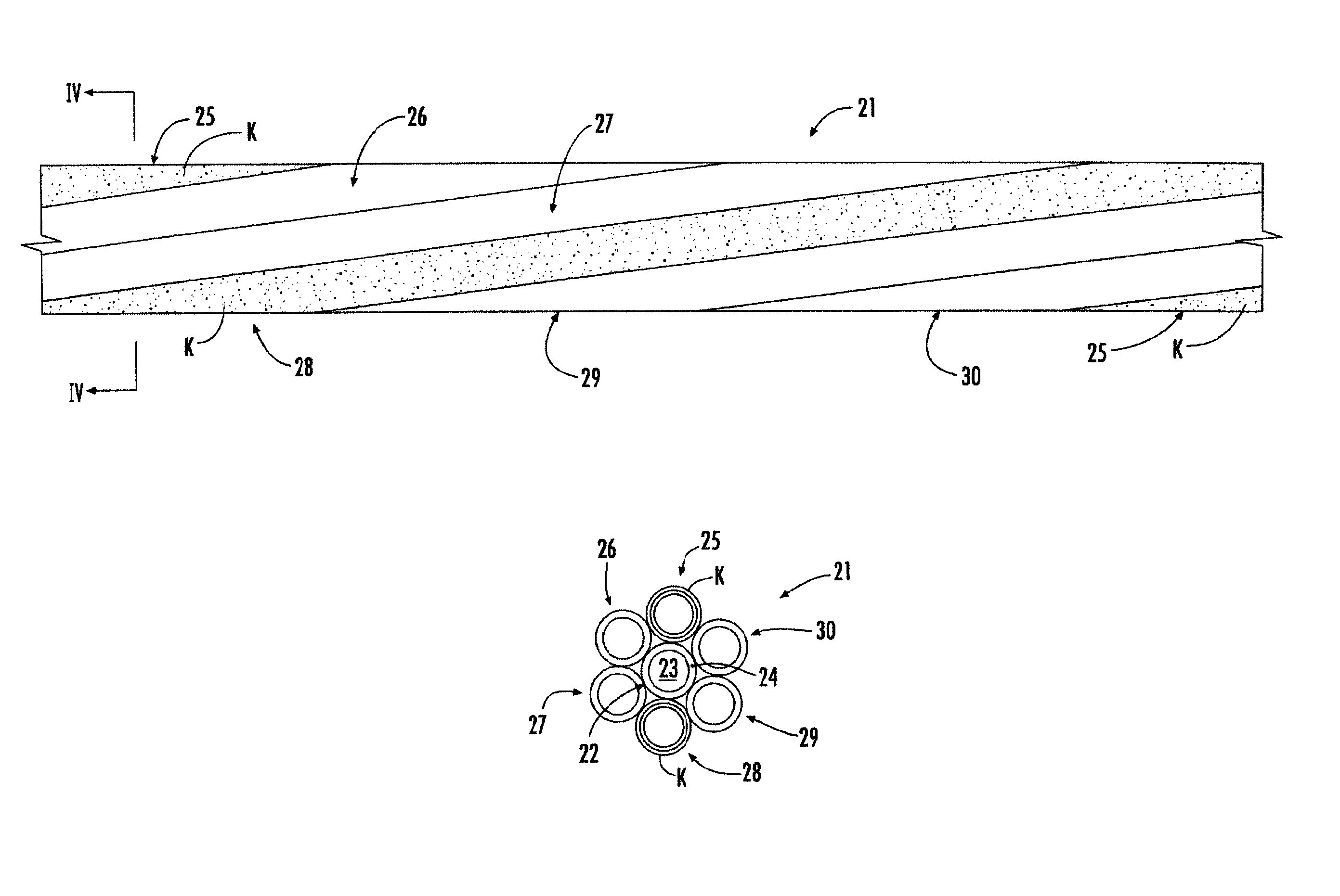
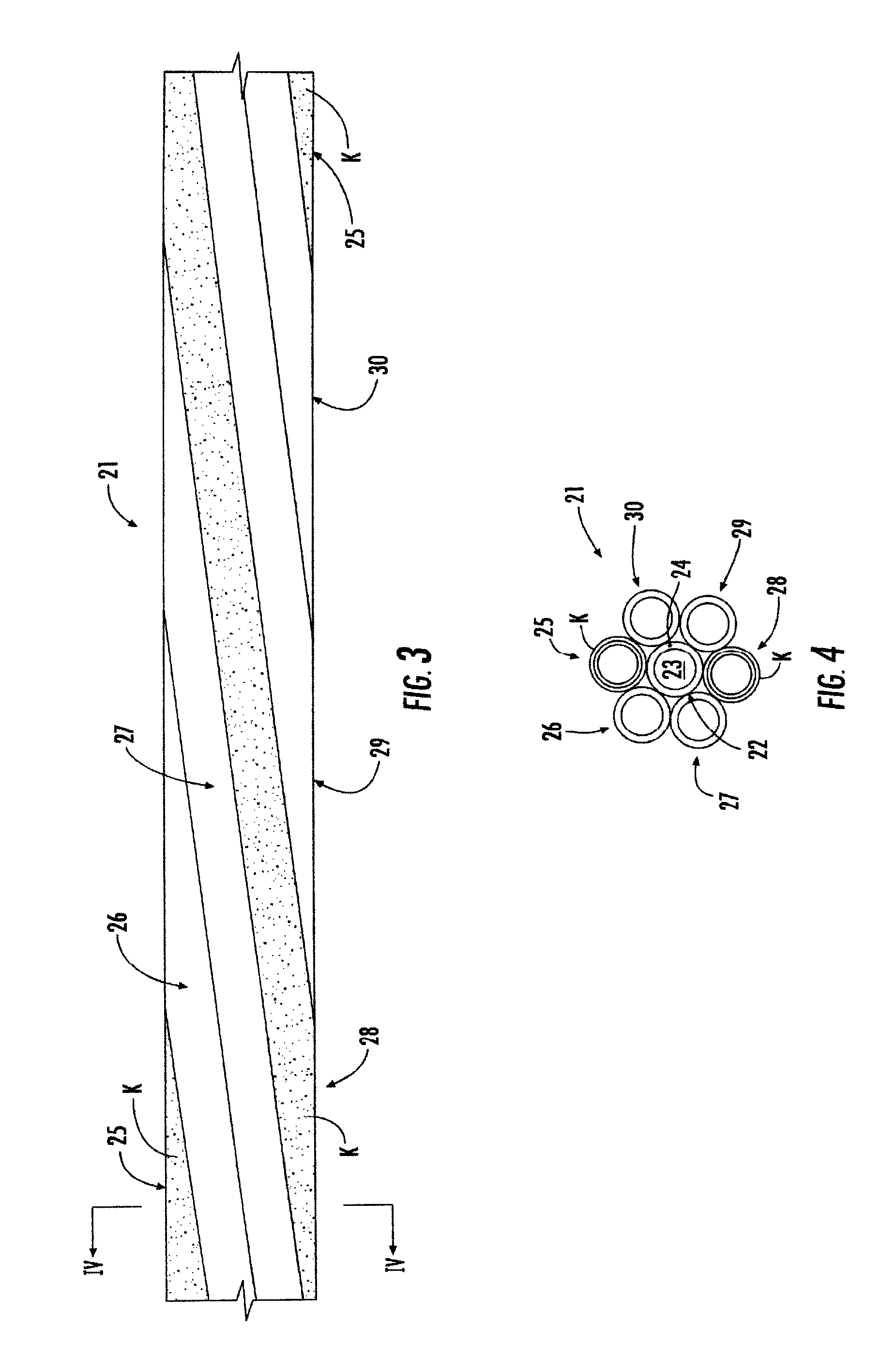
[0044]FIGS. 3 and 4 show a wire 21, such as a grounding wire, in accordance with a The wire 21 includes a center wire 22. In one instance, the center wire 22 has a steel core 23 and a copper clad layer 24 surrounding the steel core 23. However, in other instances (such as FIGS. 7 and 8), the center wire 22 could be an all steel wire.

[0045]A plurality of outer copper clad steel wires 25, 26, 27, 28, 29 and 30 are twisted around the center wire 22. Although the illustrated embodiment shows six outer CCS wires 25, 26, 27, 28, 29 and 30 around one center wire 22, other configurations could be made.

[0046]An outer coating K is formed over at least one of the plurality of outer copper clad steel wires 25, 26, 27, 28, 29 and 30. For example, in FIGS. 3 and 4, the coating K is formed over the first and fourth outer CCS wires 25 and 28. The outer coating K has an appearance which does not resemble copper, and is structured as discussed above.

third embodiment

[0047]FIGS. 5 and 6 show a wire 31, such as a grounding wire, in accordance with a The wire 31 includes a center wire 32. In one instance, the center wire 32 has a steel core 33 and a copper clad layer 34 surrounding the steel core 33. However, in other instances (such as FIGS. 7 and 8), the center wire 32 could be an all steel wire.

[0048]A plurality of outer copper clad steel wires 35, 36, 37, 38, 39 and 40 are twisted around the center wire 32. Although the illustrated embodiment shows six outer CCS wires 35, 36, 37, 38, 39 and 40 around one center wire 32, other configurations could be made.

[0049]An outer coating K is formed over at least one of the plurality of outer copper clad steel wires 35, 36, 37, 38, 39 and 40. For example, in FIGS. 5 and 6, the coating K is formed over the first, fourth and sixth outer CCS wires 35, 38 and 40. The outer coating K has an appearance which does not resemble copper, and is structured as discussed above.


PUM

PropertyMeasurementUnit
diameteraaaaaaaaaa
diameteraaaaaaaaaa
diameteraaaaaaaaaa

Abstract

A copper clad steel (CCS) wire is at least partially covered on its exterior to visibly distinguish the CCS wire from a pure / solid copper wire. A coating, such as tin, zinc or paint, covers at least portions of the CCS wire. The coating may be applied in strips, rings or a helix to identify the CCS wire as not be formed of solid copper. In the instance of a stranded CCS wire, one or more of the outer strands may be partially or entirely coated to give the overall stranded CCS wire a distinguishing outer structure.

Description

[0001]This application claims the benefit of U.S. Provisional Application No. 61 / 152,130, filed Feb. 12, 2009, the entire contents of which are herein incorporated by reference.BACKGROUND OF THE INVENTION[0002]1. Field of the Invention[0003]The present invention relates to a conductive wire. More particularly, the present invention relates to a copper clad steel (CCS) wire with an indicator to deter theft of the wire.[0004]2. Description of the Related Art[0005]Utility companies, such as companies supplying power, television, telephone, cellular services, etc., are presently experiencing a dramatic increase in theft of materials. With the value of copper being very high, copper equipment and most particularly copper wires are being stolen and sold to recycling facilities for the scrap value of the copper. Sometimes the copper is stolen from the storage lots or warehouses of the utility company or from a job site during construction. However, the more troubling and dangerous occurren...

Claims


Application Information

Patent Timeline
Patent Type & Authority Patents(United States)
IPC IPC(8): H01B7/18H01B5/00H01B5/08
CPCH01B7/365Y10T29/49117H02G2200/10
Inventor MCELLEN, ROBERTBEDDER, PAULCADY, DAVIDLAMB, JAMES
Owner BISON PATENT LICENSING LLC
Why Eureka
Try Eureka