
Digital control unit having a transient detector for controlling a switched mode power supply

a digital control unit and power supply technology, applied in the direction of electrical equipment, electrical variable regulation, instruments, etc., can solve the problems of long computation time, difficult to maintain the desired output voltage level, and the error signal fed back to the feedback unit is often too slow in changing the duty cycle, etc., to achieve compact realisation and reduce computational requirements

Active Publication Date: 2013-05-28
FLEX LTD
View PDF3 Cites 1 Cited by
  • Summary
  • Abstract
  • Description
  • Claims
  • Application Information

AI Technical Summary

Benefits of technology

The patent describes a new method for detecting transients in an input signal and controlling the duty cycle of a switched mode power supply. This method saves power and computation time by not applying VFF compensation when no transient has been detected. Additionally, this method is effective at detecting reliably and accurately transients while being able to handle measurement noise and light load-induced noise. The technical effects achieved by this patent are efficient and effective detection of transients and improved control of the duty cycle of a switched mode power supply.

Problems solved by technology

However, it is difficult to maintain the desired output voltage level due to transients on the input signal.
In addition the error signal fed back to the feedback unit is often too slow in changing the duty cycle and so a large transient is introduced on the output voltage.
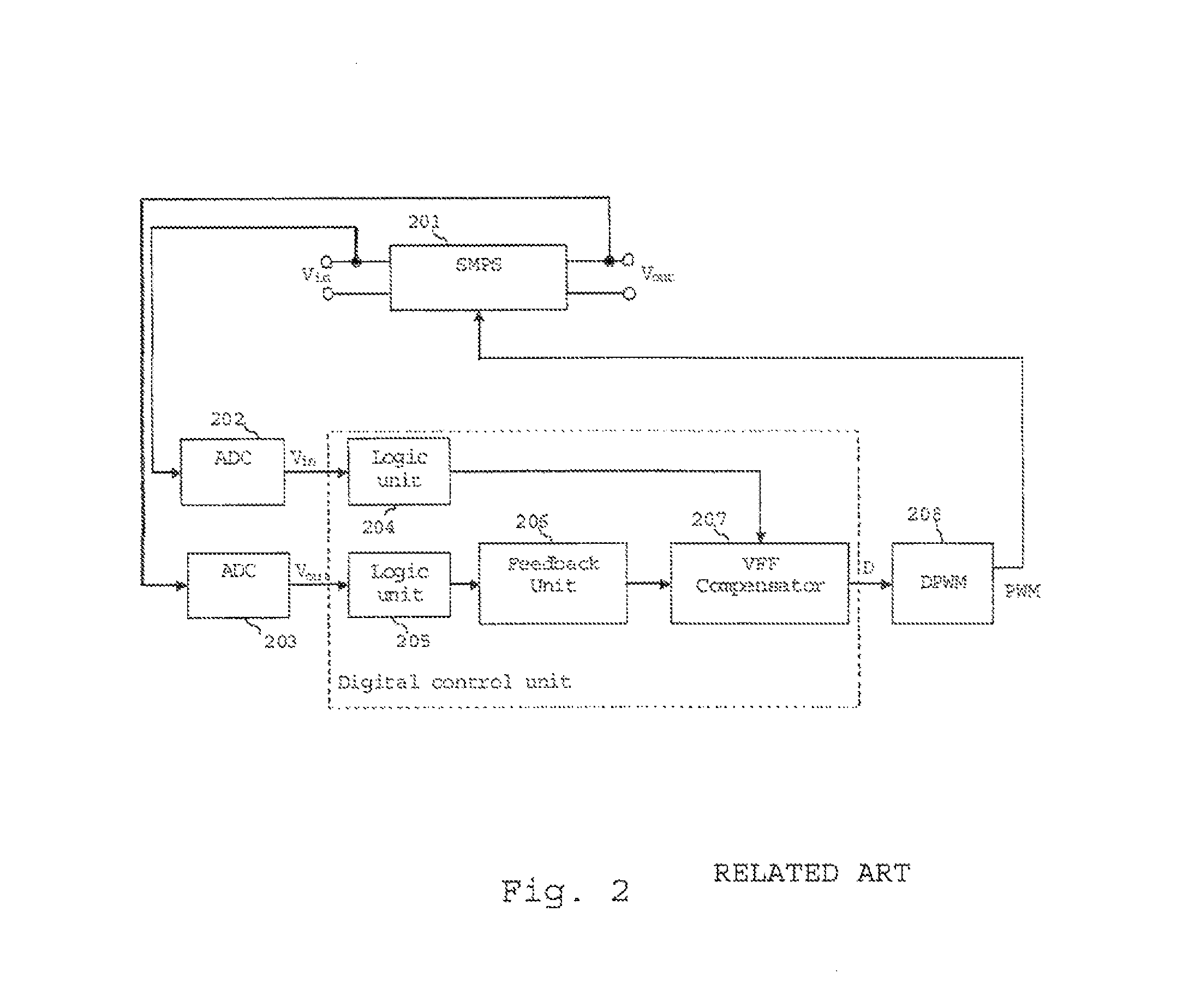
A problem experienced by the above described SMPS controllers, that use a feedback unit and a VFF compensator, is that the calculation of the compensation signal and the calculation of a duty cycle control signal by the feedback unit results in long computation times and increased power consumption.
Moreover, the complex and time consuming division operation with an additional multiplication has to be performed every switch period even when the input voltage is stable.
However, DSPs are expensive, have a high power-consumption and long computation times. DSPs are also large and not suitable for use in compact applications.
An additional problem with known digital VFF compensation signal generators is that when the voltage of the input signal is located near a quantization level of the ADC for measuring the input signal, noise can cause the quantized version of the input signal to change.
A further problem is experienced when the input signal is changing slowly and feedback is compensating for the changes.
Yet a further problem with known SMPS controllers is that at light load, energy can be transferred back and forth in isolated.
This also triggers the VFF compensation and introduces output voltage noise.

Method used


Image

  • Digital control unit having a transient detector for controlling a switched mode power supply
  • Digital control unit having a transient detector for controlling a switched mode power supply
  • Digital control unit having a transient detector for controlling a switched mode power supply

Examples


first embodiment

[0148]According to a first embodiment, the above described transient detector 701 is incorporated into a digital control unit for an SMPS.

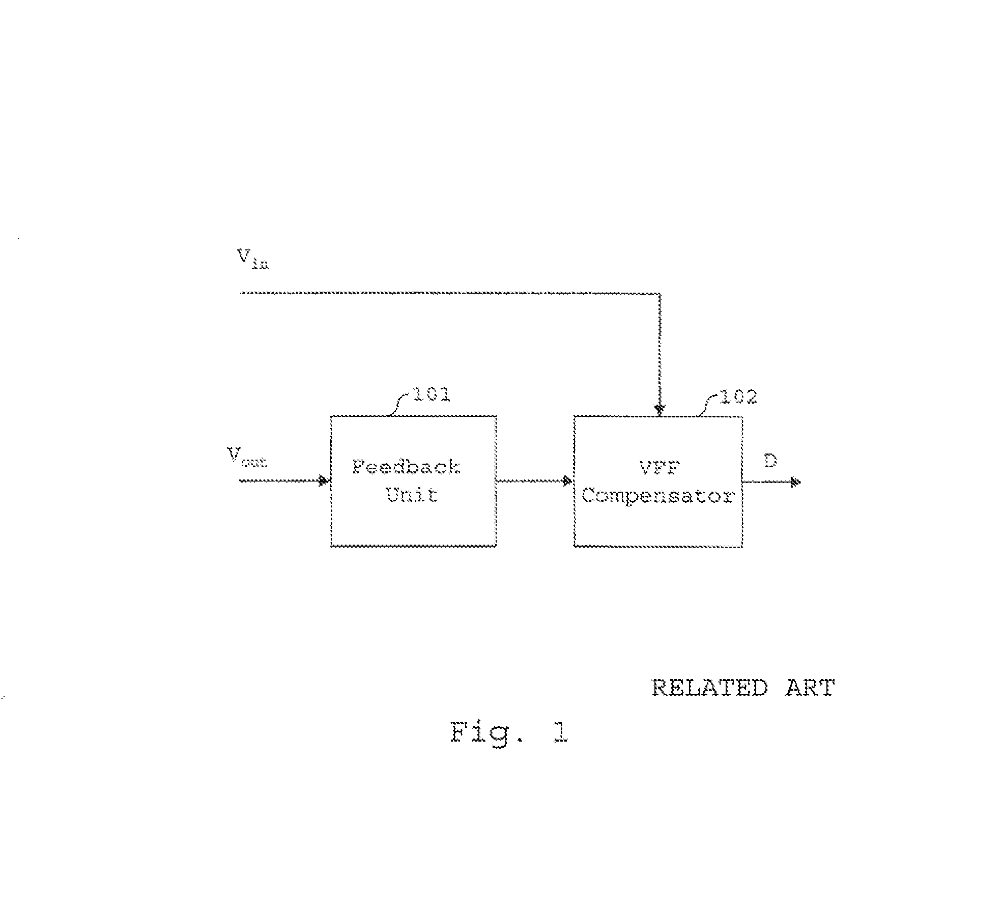
[0149]FIG. 6 is a block diagram of the digital control unit 401 of the first embodiment, in which a VFF compensator 450 and transient detector 701 are integrated into a feedback unit.

[0150]Advantageously, the integration of the VFF compensator into the digital control unit allows a more compact realisation of the digital control unit.

[0151]In addition, the algorithms used in the VFF compensation can result in reduced computational requirements.

[0152]A more detailed circuit diagram of the digital control unit 401 according to the first embodiment is shown in FIG. 7.

[0153]Referring to FIG. 7, input port 2 receives an error signal, Vout—err, which represents the difference between the measured output voltage and the desired output voltage of the SMPS.

[0154]The input signal Vout—err is fed into an arrangement of delay elements 504 and 505 as well as a...

second embodiment

[0182]The second embodiment of the invention differs from the first embodiment in the way in which the VFF compensation signal is calculated and applied.

[0183]In the second embodiment, the calculated VFF compensation signal is an approximation of the VFF compensation given in Equation 7.

[0184]An advantage of the second embodiment over the previous embodiment of the invention is that the division operation performed by computation block 502 in FIG. 7 is avoided and this significantly simplifies the computational requirements of the digital control unit.

[0185]Defining the change in input voltage ΔV as:

Vin-new=Vin-old−ΔV  Equation 12

[0186]An approximate VFF compensation signal can be obtained using the updated duty cycle:

[0187]Dnew=⁢Dold⁡(1+Δ⁢⁢VG)=⁢Dold+Dold⁢Δ⁢⁢VGEquation⁢⁢13

[0188]In Equation 13, the new duty cycle, Dnew, is changed with a factor (1+ΔVG). The change in the input voltage ΔV is scaled with a factor G. The output voltage becomes:

[0189]Vout=⁢Vin-new⁢Dnew=⁢(Vin-old-Δ⁢⁢V)⁢Do...

third embodiment

[0203]In a third embodiment of the invention, a different circuit from the second embodiment is used to calculate and apply the VFF compensation signal.

[0204]From Equation 13, it is clear that the duty cycle is updated with a gain factor, C.

[0205]Dnew=⁢Dold⁡(1+Δ⁢⁢VG)=⁢Dold·C⁢⁢where,⁢C=1+Δ⁢⁢VGEquation⁢⁢16

[0206]The gain G is calculated as shown in Equation 15 and, as described for Equation 15, can be approximated to a constant.

[0207]A digital control unit according to the third embodiment which controls the duty cycle in accordance with Equation 16 is shown in FIG. 10.

[0208]The digital control unit of the third embodiment differs from the second embodiment in that the multiplier 903 has been replaced with an adder 1101 and a constant value generator 1102, and adder 906 has been replaced by multiplier 511.

[0209]In the third embodiment, the output of amplifier 902 is input to adder 1101. Constant value generator 1102 generates and outputs a constant value (which comprises the value “1” ...


PUM


Abstract

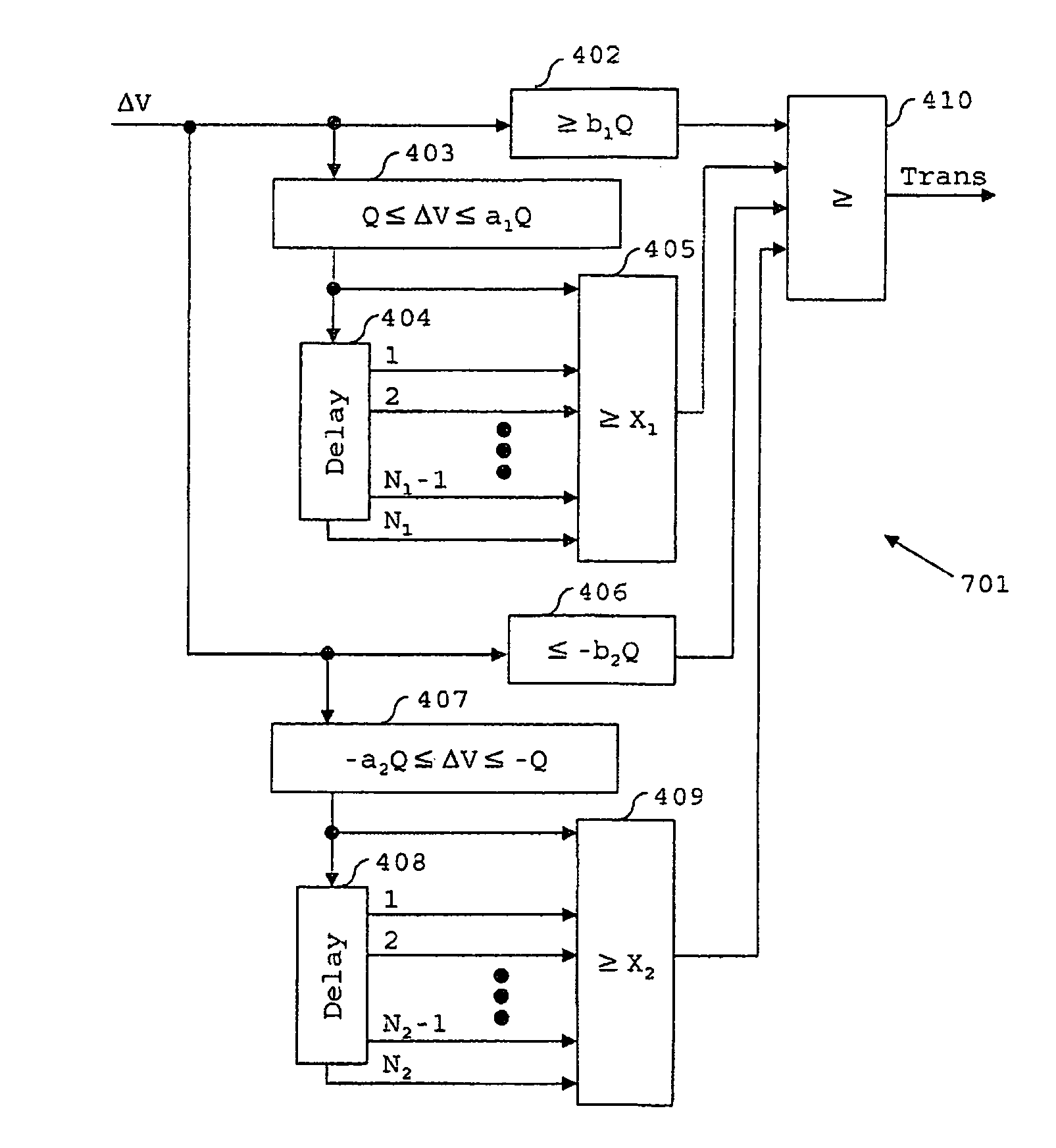
A switched mode power supply (SMPS) comprising a feedback unit, voltage feed forward (VFF) compensation signal generator and a transient detector. A VFF compensation signal is only applied to the output of the feedback unit when a transient is detected by the transient detector on the input voltage of the SMPS, thereby saving power and computation time. The transient detector comprises a first comparator to detect that a positive transient has occurred if a difference signal is greater than a positive threshold level; a second comparator to determine if the difference signal is within a predetermined range of positive values and output a result that indicates if the difference signal is within the predetermined range of positive values; and a first calculator to detect that a positive transient has occurred if, out of a first predetermined number of consecutive results of the output of the second comparator, there is at least a second predetermined number of results indicating that the difference signal is within the predetermined range of positive values. The transient detector comprises further features for similarly detecting a negative transient.

Description

TECHNICAL FIELD[0001]The present invention relates generally to the field of switched mode power supplies (sometimes referred to as switch mode power supplies or switching mode power supplies) and more specifically to a digital control unit for a switched mode power supply, the digital control unit having a transient detector for detecting a transient on an input signal to the switched mode power supply.BACKGROUND[0002]The switched mode power supply (SMPS) is a well-known type of power converter having a diverse range of applications by virtue of its small size and weight and high efficiency. For example, SMPSs are widely used in personal computers and portable electronic devices such as cell phones. An SMPS achieves these advantages by switching a switching element such as a power MOSFET at a high frequency (usually tens to hundreds of kHz), with the frequency or duty cycle of the switching being adjusted using a feedback signal to convert an input voltage to a desired output volta...

Claims


Application Information

Patent Timeline
Patent Type & Authority Patents(United States)
IPC IPC(8): G05F1/00
CPCH02M3/156H02M2001/0022H02M1/0022
Inventor KARLSSON, MAGNUSBORGENGREN, HENRIKKULLMAN, ANDERSMALMBERG, JONASWAHLEDOW, FREDRIK
Owner FLEX LTD
Learn More