Laminated RF device with vertical resonators having stack arrangement of laminated layers including dielectric layers

a technology of vertical resonators and laminated layers, which is applied in the direction of resonators, waveguides, antennas, etc., can solve the problems of increased interference possibility between different systems, communication systems that require an extremely high frequency selectivity, and the decrease of resonator devices, so as to facilitate the provision of selective cross-coupling and facilitate the manufacturing process

Inactive Publication Date: 2013-05-28
PANASONIC CORP
View PDF17 Cites 10 Cited by
  • Summary
  • Abstract
  • Description
  • Claims
  • Application Information

AI Technical Summary

Benefits of technology

[0032]This construction has the advantage that the effective outer diameter Do of the (pseudo) coaxial transmission line, i.e. of the corresponding coaxial transmission line, can be significantly increased as compared to prior art laminated type resonator devices having a strip-line transmission line extending in the direction of extension of the dielectric layers, while at the same time allowing for a compact design. In this manner, the ratio of effective outer diameter to effective inner diameter can be increased yielding a higher characteristic impedance and higher inductivity values of the transmission line formed in part by the via hole(s) and extending transverse to the direction of extension of the dielectric layers and in particular in the stacking or vertical direction. Further, the volume of the resonator is increased yielding higher quality factors. In addition, due to the possibility to decrease the aspect ratio of the via hole conductors as compared to the inner strip-line conductor layers of the prior art devices described above, the electric current is distributed more homogeneously, thereby reducing conductor losses and further increasing the quality factor. Maximum homogenization can be achieved in a preferred embodiment in which the via hole conductors have a cylindrical configuration with circular or oval cross sectional shape. Finally, there is a greater flexibility in arranging the resonator or parts of the resonator within the laminate.
[0054]In case of resonator devices having at least two resonators, the at least two resonators may comprise at least one group of two resonators that are arranged, in the stacking direction, one upon the other and are electromagnetically coupled. Such a resonator device will, of course, have at least twice the thickness, in the stacking direction, than a resonator device that only includes resonators arranged side by side. However, it is possible to achieve more flexibility in coupling arrangements between a plurality of resonators.

Problems solved by technology

The growing number of microwave applications increases the possibility of interference occurring within a system or between different systems.
Thus, such communication systems require an extremely high frequency selectivity in both the base stations and the mobile devices which often approaches the theoretical limit.
In reality, such resonators are always shorter than one quarter wavelength, because the open circuit cannot be ideally realized due to fringe fields that are always present at the open end which therefore acts as a capacitor.
Furthermore, since the volume of the resonator device is decreased, the stored energy is limited.
Usually, for a suitably chosen dielectric material dielectric losses are lower than conductor losses, i.e. Qc is limiting the overall quality factor.
However, in the prior art devices of the laminated type including strip-line transmission lines extending in the direction of extension of the dielectric layers or horizontal direction, the quality factor achievable is still limited, and known measures for improving the quality factor add complexity and costs to the manufacturing processes.
However, this reference does not disclose a resonator device including a resonator comprising a transmission line, in particular a (pseudo) coaxial transmission line.

Method used


Image

  • Laminated RF device with vertical resonators having stack arrangement of laminated layers including dielectric layers
  • Laminated RF device with vertical resonators having stack arrangement of laminated layers including dielectric layers
  • Laminated RF device with vertical resonators having stack arrangement of laminated layers including dielectric layers

Examples


Embodiment Construction

[0136]In the following, exemplary preferred embodiments of the invention are described in more detail with reference to the drawings. Throughout the figures, similar and corresponding parts are designated by the same reference numerals.

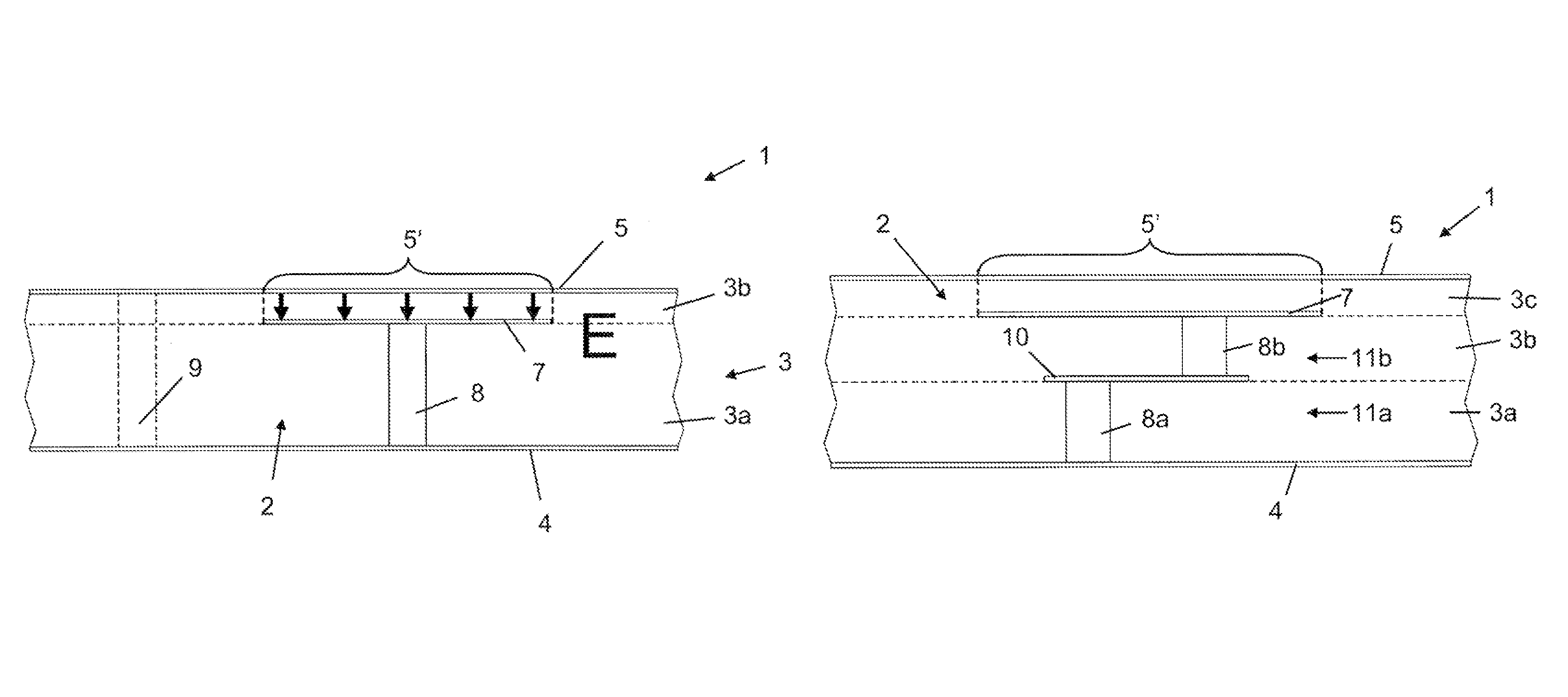
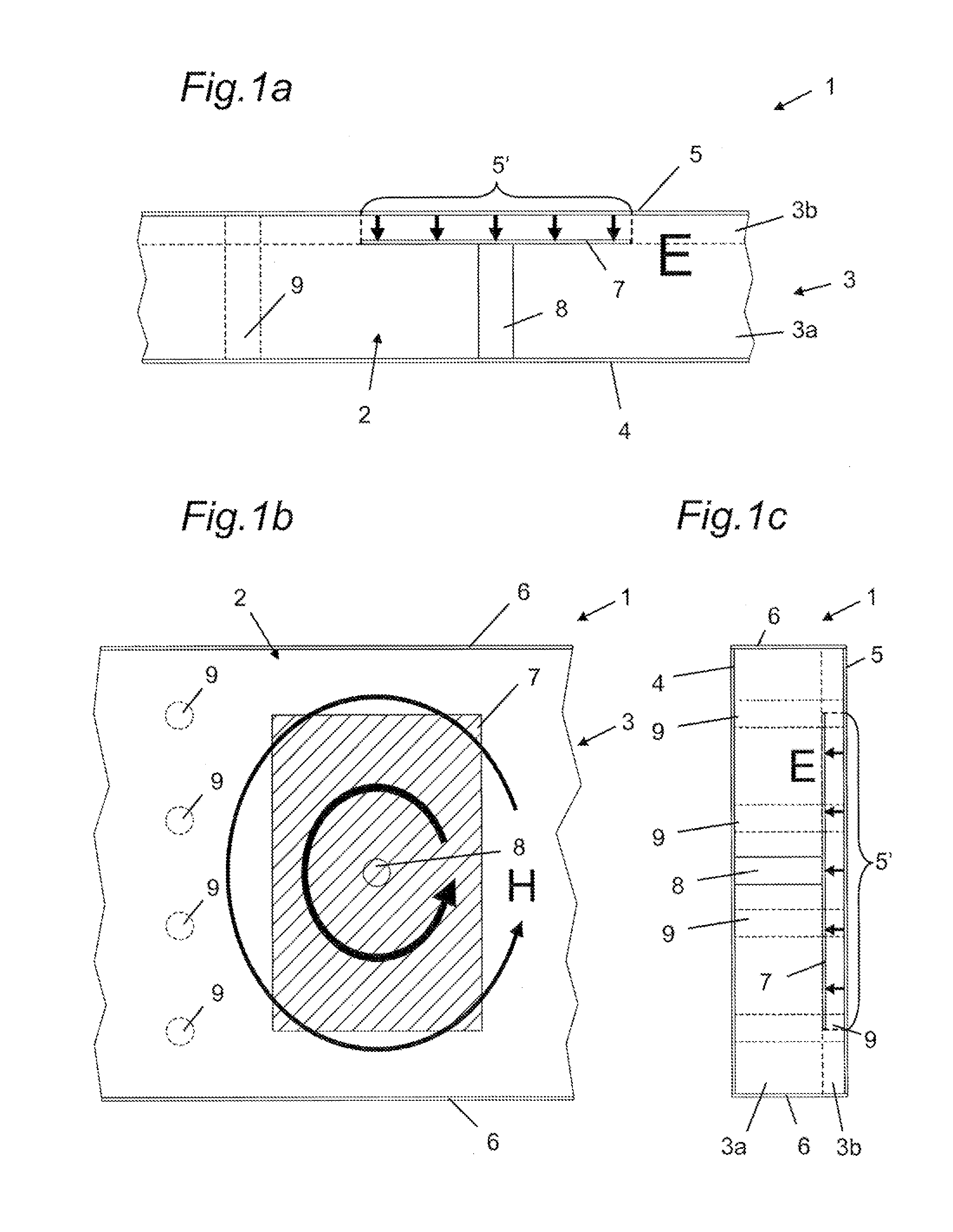
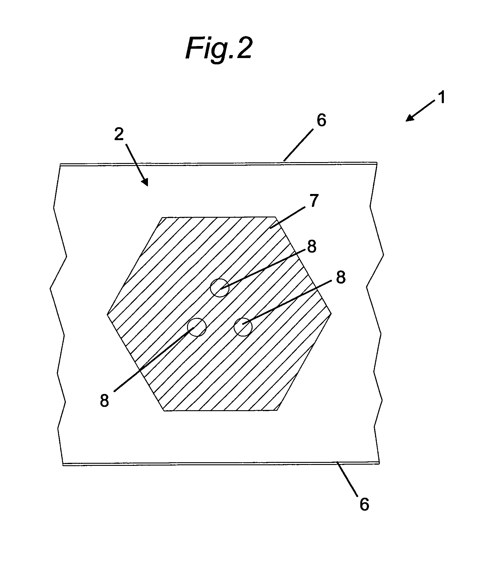
[0137]In FIG. 1a a resonator device 1 having only one resonator 2 is shown in schematic cross sectional side view. The same resonator device 1 is shown in schematic top view in FIG. 1b and in cross sectional end view in FIG. 1c. The resonator device 1 comprises a laminate 3 that includes a plurality of sheets 3a, 3b made of dielectric material and stacked on top of each other and laminated together. This laminate 3, in which the sheets 3a, 3b constitute layers of the laminate, can be regarded as the main body of the resonator device or a substrate into which main body or substrate components of the resonator 2 to be described in the following are incorporated or embedded. It is to be understood that the sheet 3a and / or the sheet 3b may be replaced by ...


PUM

PropertyMeasurementUnit
frequency bandaaaaaaaaaa
thicknessaaaaaaaaaa
widthaaaaaaaaaa

Abstract

The present invention relates to a resonator device having a stacked arrangement of laminated layers including a plurality of dielectric layers, and at least one resonator comprising a short-circuit electrode, a first capacitor electrode and a second capacitor electrode. Each electrode comprises at least a portion of a layer of electrically conductive material provided on a surface of one of the dielectric layers. The second capacitor electrode is disposed spaced, in the stacking direction, from the short-circuit electrode and the first capacitor electrode. The short-circuit electrode and the second capacitor electrode are electrically interconnected by a first electrical connection comprising at least one via hole penetrating one or more of the dielectric layers.

Description

TECHNICAL FIELD[0001]The present invention relates to a resonator device having a stacked arrangement of laminated layers, including a plurality of dielectric layers, and at least one resonator comprising a short-circuit electrode, a first capacitor electrode and a second capacitor electrode, each electrode comprising at least a portion of a layer of electrically conductive material provided on a surface of one of the dielectric layers. Further, the present invention relates to an RF device, such as a microwave filter or duplexer, comprising such a resonator device and to a method of manufacturing such a resonator device.BACKGROUND ART[0002]The microwave region of the electromagnetic spectrum finds widespread use in various fields of technology. Exemplary applications include wireless communication systems, such as mobile communication and satellite communication systems, as well as navigation and radar technology. The growing number of microwave applications increases the possibili...

Claims


Application Information

Patent Timeline
Patent Type & Authority Patents(United States)
IPC IPC(8): H01P7/00H03H7/00H01P3/00
CPCH01P1/202H01P1/203H01P7/08H01P7/04Y10T29/49016
Inventor HOEFT, MICHAELISHIZAKI, TOSHIONAKAKUBO, HIDEAKI
Owner PANASONIC CORP
Why Eureka
Try Eureka