
Method for determining biases of satellite signals

a satellite signal and bias technology, applied in the field of satellite signal bias detection, can solve problems such as information loss, and achieve the effect of improving accuracy

Active Publication Date: 2013-05-28
DEUTSCHES ZENTRUM FUER LUFT & RAUMFAHRT EV
View PDF3 Cites 13 Cited by
  • Summary
  • Abstract
  • Description
  • Claims
  • Application Information

AI Technical Summary

Benefits of technology

The invention provides a method with improved accuracy for determining systematic instrumental errors in a navigation system. The method separates individual values for instrumental code biases and instrumental ambiguity-free phase biases of satellites and reference stations, as well as phase ambiguities of the satellite signals. This allows for more accurate determination of the phase biases and reduces the number of unknowns, resulting in improved accuracy of the navigation system.

Problems solved by technology

By determining separate individual values for code biases and elementary phase biases these systematic instrumental errors can be determined with much higher accuracy than in conventional methods, in which a common bias is determined for satellites and reference stations or in which phase biases of the satellites and reference stations ambiguities are lumped with the biases, resulting in a loss of information, since the information that the ambiguities must be integer valued is not used.

Method used


Image

  • Method for determining biases of satellite signals
  • Method for determining biases of satellite signals
  • Method for determining biases of satellite signals

Examples


Embodiment Construction

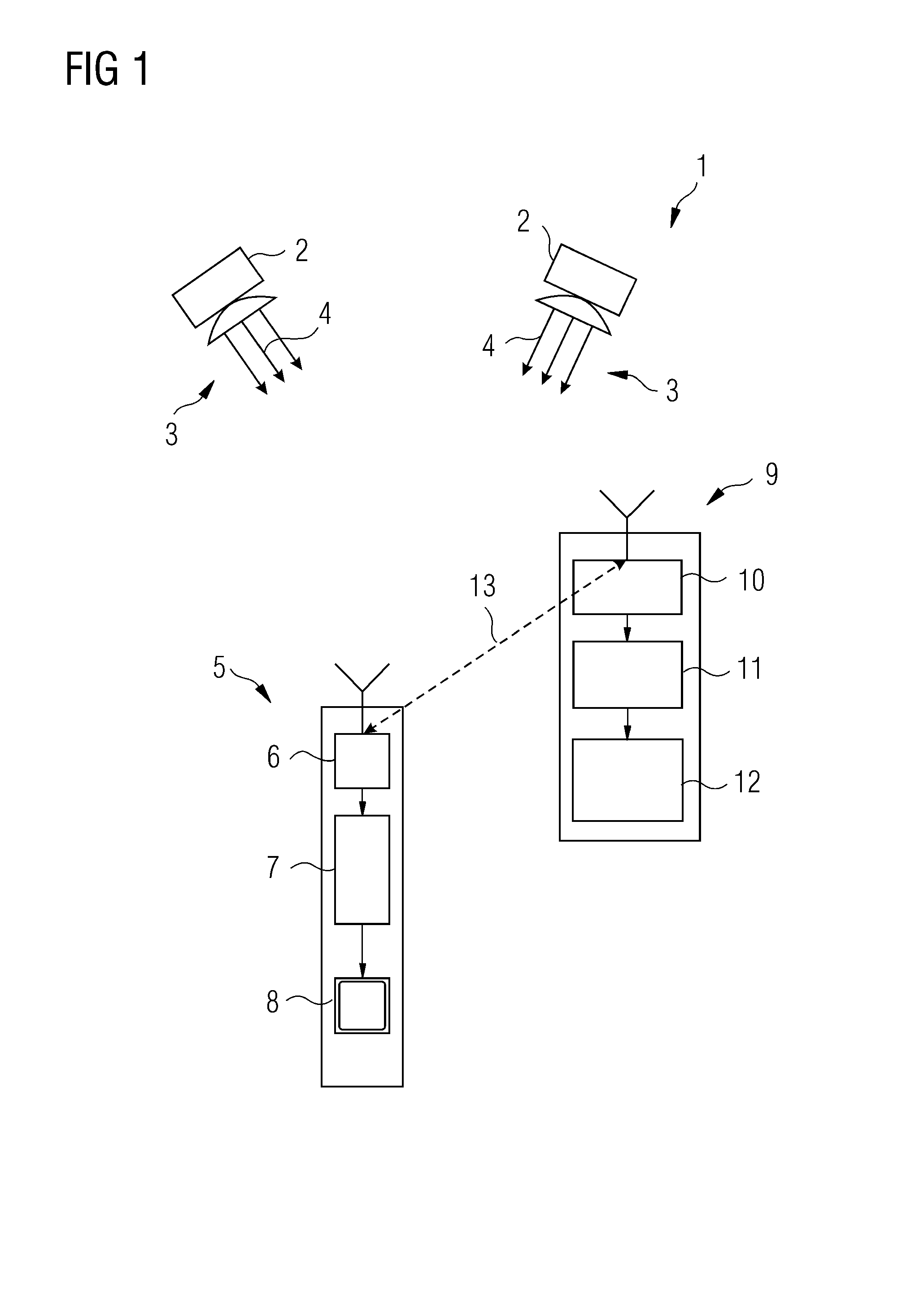
[0043]FIG. 1 shows a global navigation satellite system 1 which comprises satellites 2 orbiting around the earth and emitting navigation signals 3 modulated on a number of carrier signals 4.

[0044]A user system or navigation device 5 comprises a receiver 6 which is connected to a signal processor 7. The signal processor 7 processes the navigation signal 3 received from the satellites 2 and displays the results on a display 8 of the navigation device 5.

[0045]A stationary reference station 9 equally comprises a receiver 10 connected to a signal processor 11 and a transmission unit 12, which transmitts system informations to the navigations devices 5. In particular the satellite biases and information on the ionospheric delay are transmitted to the navigations devices 5.

[0046]For determining the position of the navigation device 5 various methods can be used. Generally code measurements of code signals transmitted by the carrier signals and phase measurement of the actual phase of the c...


PUM


Abstract

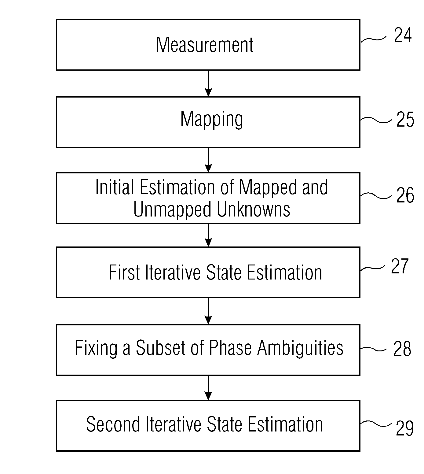
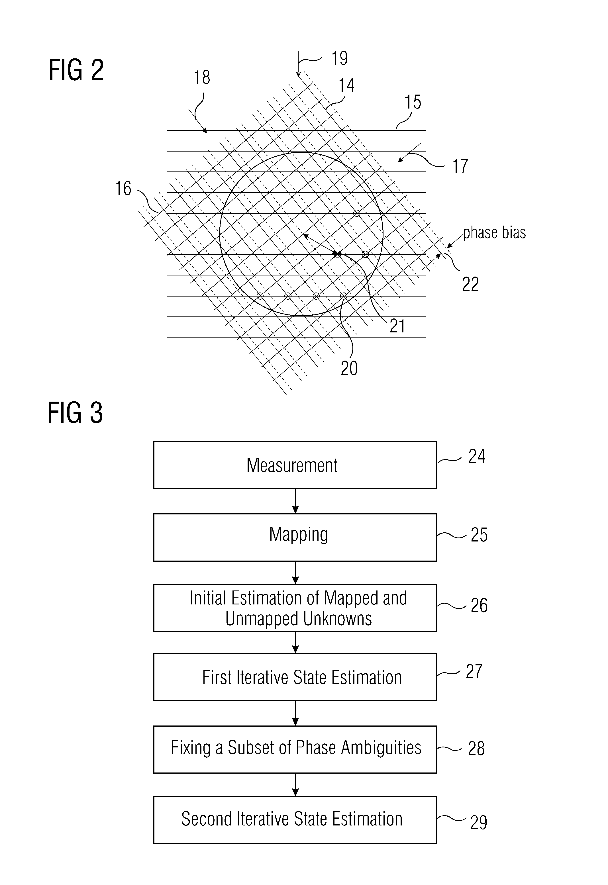
A new method for bias estimation on multiple frequencies with a Kalman filter is proposed. It consists of four steps: First, a least-squares estimation of ranges, ionospheric delays, ambiguities, receiver phase biases and satellite phase biases is performed. The code biases are absorbed in the ranges and ionospheric delays, and a subset of ambiguities is mapped to the phase biases to remove linear dependencies between the unknown parameters. In a second step, the accuracy of the bias estimates is efficiently improved by a Kalman filter. The real-valued a posteriori ambiguity estimates are decorrelated by an integer ambiguity transformation to reduce the time of ambiguity resolution. Once the float ambiguities have sufficiently converged, they are fixed sequentially in a third step. Finally, a second Kalman filter is used to separate the receiver and satellite code biases and the tropospheric delays from the ranges.

Description

CROSS-REFERENCE TO RELATED APPLICATION[0001]This present application claims priority of European patent application No. EP 09 178 573.3 filed on Dec. 9, 2009, the disclosure of which is hereby incorporated by reference in its entirety as part of the present disclosure.FIELD OF THE INVENTION[0002]The invention relates to a method for determining biases of satellite signals emitted by satellites of a satellite navigation system and received by reference stations comprising the acts:[0003]receiving the satellite signals of the satellites by a plurality of reference stations, and[0004]determining systematic instrumental errors based on the satellite signals received from the satellites by using a recursive state estimator.BACKGROUND OF THE INVENTION[0005]Such a method is known from E. SARDON, A. RIUS, N. ZARRAOA: “Estimation of the transmitter and receiver differential biases and the ionospheric total electron content from Global Positioning System observations” Radio Science, vol. 29, ...

Claims


Application Information

Patent Timeline
Patent Type & Authority Patents(United States)
IPC IPC(8): G01S19/07
CPCG01S19/04G01S19/32G01S19/44
Inventor HENKELWEN, ZHIBOGUENTHER, CHRISTOPH
Owner DEUTSCHES ZENTRUM FUER LUFT & RAUMFAHRT EV
Learn More