Cooling device for a plurality of power modules

a power module and cooling device technology, applied in the direction of cooling/ventilation/heating modification, electrical apparatus, heat exchange apparatus, etc., can solve the problems of complex assembly of individual modules, unfavorable cooling effect distribution over all modules, and high cost, and achieve uniform cooling performance, easy assembly, and the effect of avoiding leakag

Inactive Publication Date: 2013-05-28
DANFOSS SILICON POWER
View PDF23 Cites 12 Cited by
  • Summary
  • Abstract
  • Description
  • Claims
  • Application Information

AI Technical Summary

Benefits of technology

[0007]The invention is therefore based on the task of providing a cooling device that permits a stacked design of a plurality of power modules in a space-saving and easily assembled manner and which at the same time permits a uniform cooling performance on all modules in a safe manner without the risk of leakages.
[0010]Further, the simple, stack-shaped arrangement of the modules enables the realisation of a simple, low-inductance bus, and a common, mechanical protection of the modules, and of the wedges, against slipping.
[0011]Further, the advantage occurs that the sealing for the water cooling on the side facing away from the modules can be distant from the electronic components, so that the insertion of several sealing layers is possible. Still a compact, space-saving design with a simple assembly occurs, as all module interfaces are clearly visible.
[0013]In this case, adjacent arrangement of the stack modules means that they are aligned parallel to each other in a row, their flat sides facing each other. Advantageously, in this connection the fins have approximately the same dimensions as a power module. However, due to the inserts that are preferably provided for channel forming walls, the fins are made thicker. A protrusion over the dimensions of the power module would make assembly somewhat more difficult; on the other hand; however, in certain cases this will mechanically protect the connections in an advantageous manner.
[0014]Wedges, which are advantageously provided to correspond to guiding rails in the power modules, and which can be fixed by an final support that can be fitted across all fins by means of screws, can provide a heat conductive, secure contact of the power modules in the cooling arrangement. In this connection, the material of the wedges can, like the material of the modules, be adapted to the expansion of the cooling device, in particular that of the basic support carrying the fins.
[0017]As can be seen, a soldered embodiment variant does not require protection of the modules by a moulded element, as a wedge pressing is not required.

Problems solved by technology

In cooling devices as known from, for example, DE 103 58 641 A1, the embodiment of the cooler is very expensive, therefore cost intensive, and the assembly of the individual modules is complicated.
Further, here the problem occurs that the cooling effect is not distributed in a uniform manner over all modules.
An alternative, that of direct cooling, has the disadvantage that a sealing of the water transferring areas in the vicinity of the electronics is required, and that the operating conditions with long operating times of the electronics and the comprehensive damage that can result from an electronics failure have meant that until now the risk of possible leakages in the state of the art devices have most frequently prevented the use of an open water cooler.
The classic method with a cooling plate only permits the planar arrangement of modules and thus requires a substantially larger base than a stacked design.
Further, also the module assembly is expensive here.
These complex structures involve increased leakage risks, as the coolant channels are often bent and exposed to mechanical influences.
Due to their complexity, these devices can only be manufactured at high costs.

Method used


Image

  • Cooling device for a plurality of power modules
  • Cooling device for a plurality of power modules
  • Cooling device for a plurality of power modules

Examples


Embodiment Construction

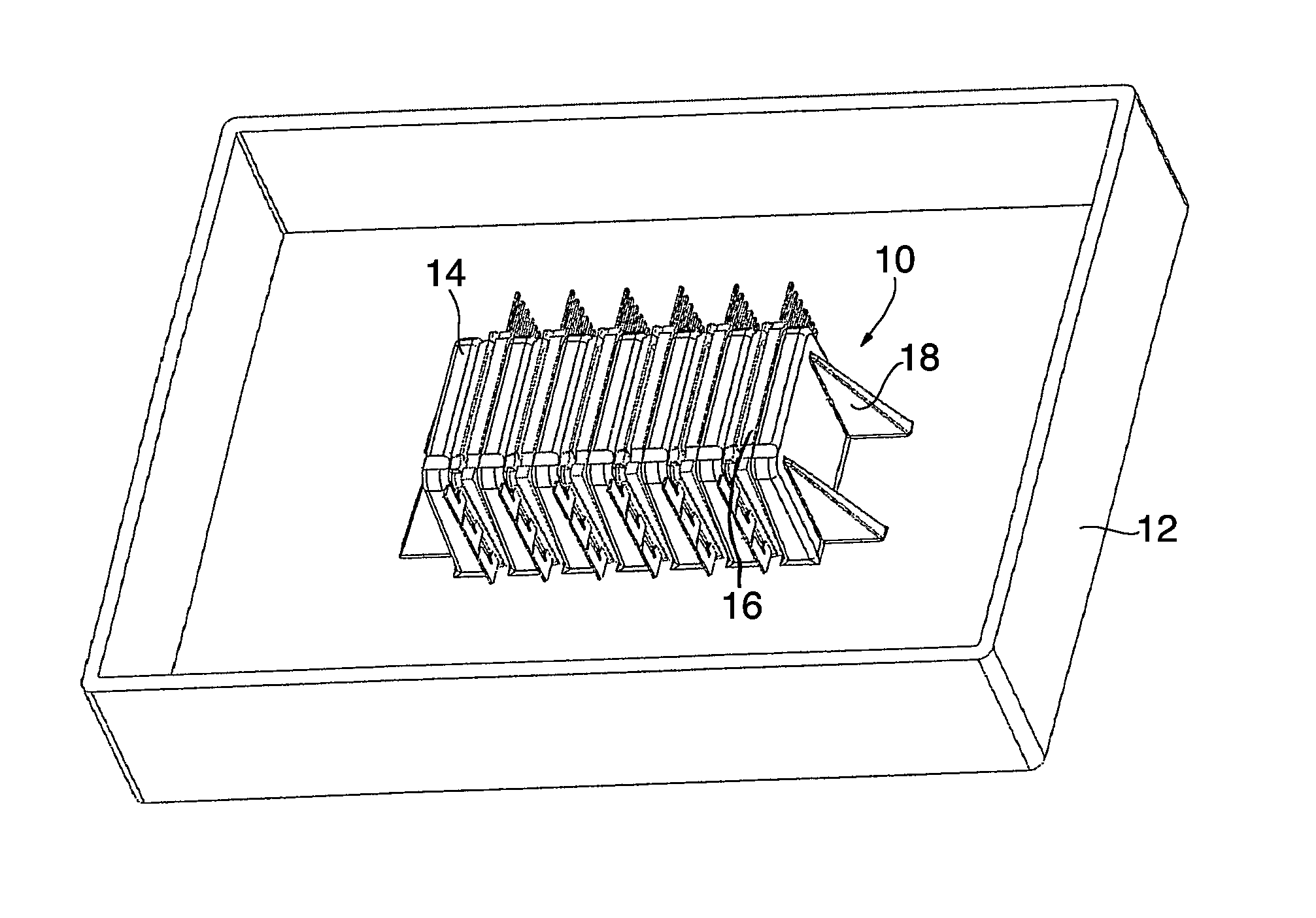
[0025]The outer frame 12 visible around the cooling device 10 in FIG. 1 serves for the accommodation of further components.

[0026]The device, and in particular the individual cooling fins 14, which extend parallel to and are arranged adjacent to each power module 16, have approximately the same height as the power modules in order to contact all areas in which heat can occur.

[0027]For example, the drawing shows six power modules 16 surrounded by seven cooling fins 14, each outer cooling fin 14 also comprising a support edge 18. Aluminium is suggested as a material for the cooling body, but also other materials can be imagined.

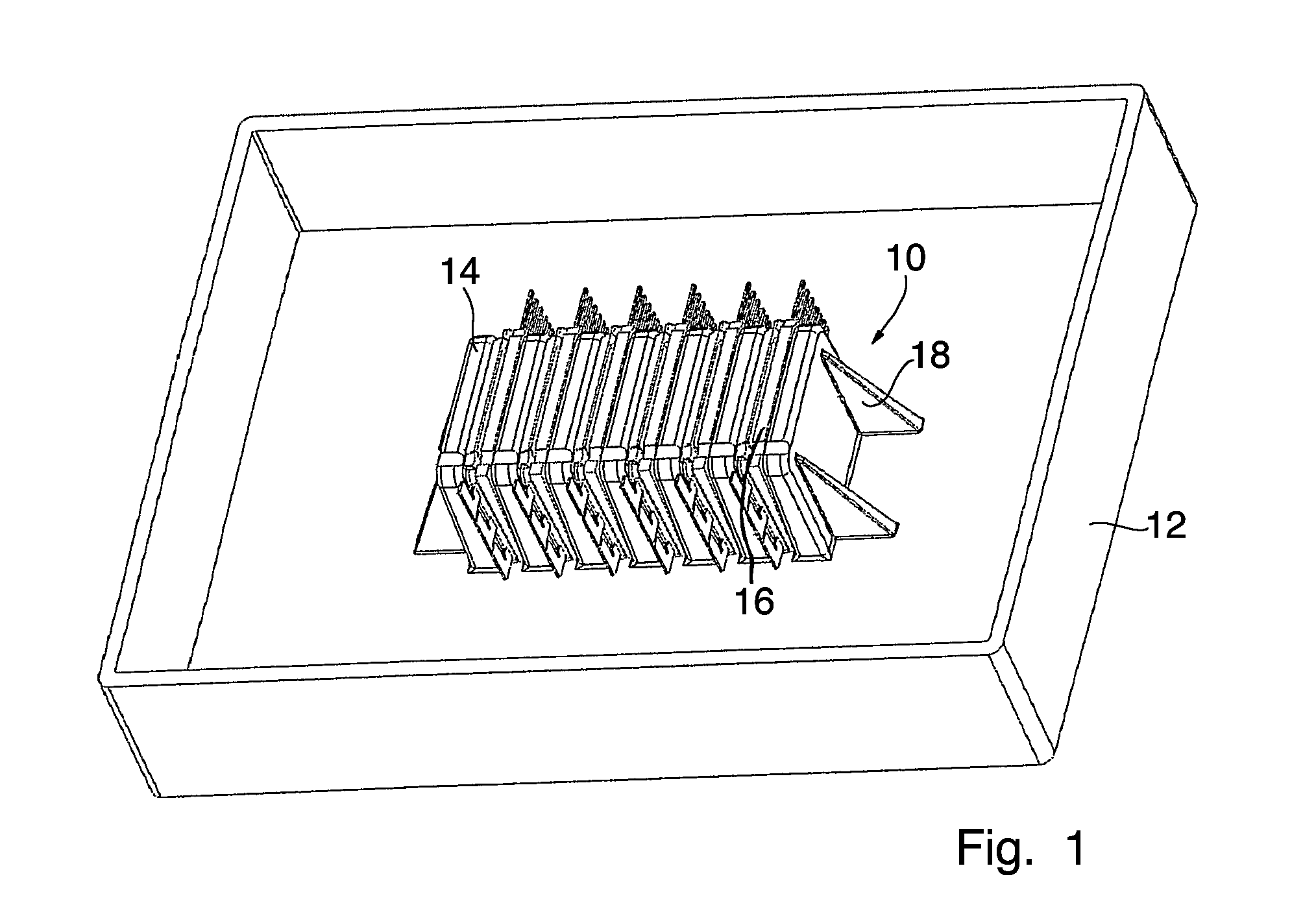
[0028]Not visible in FIG. 1 are the features shown in FIG. 2, namely the plates 20 inserted into the individual cooling fins from below for forming coolant channels, and a cover support 22 arranged above the fins and having screw bolt connections for fixing the wedges.

[0029]Clearly visible on a first housing shell 24 of the body 15, through which the coolant flo...


PUM


Abstract

The invention relates to a cooling device for a plurality of power modules (16), comprising a heat-conducting body (15) through which a coolant flows. The cooling device comprises external cooling ribs (14) on a first housing shell of the body through which a coolant flows for receiving the plurality of power modules adjacent to each other. Each individual cooling rib is aligned to come into fixed heat-conducting contact on at least one upper or lower side of one of the plurality of power modules, and the housing shell, on the inner side in the region of the respective cooling rib(s), comprises means for the fluidic communication with the volume of the coolant in the inside the body through which the coolant flows.

Description

CROSS REFERENCE TO RELATED APPLICATIONS[0001]This application is entitled to the benefit of and incorporates by reference essential subject matter disclosed in International Patent Application No. PCT / DE2009 / 000561 filed on Apr. 27, 2009 and German Patent Application No. 10 2008 021 917.7 filed May 2, 2008.FIELD OF THE INVENTION[0002]The invention concerns a cooling device for a plurality of power modules according to the preamble of the main claim.BACKGROUND OF THE INVENTION[0003]In cooling devices as known from, for example, DE 103 58 641 A1, the embodiment of the cooler is very expensive, therefore cost intensive, and the assembly of the individual modules is complicated. Further, here the problem occurs that the cooling effect is not distributed in a uniform manner over all modules.[0004]An alternative, that of direct cooling, has the disadvantage that a sealing of the water transferring areas in the vicinity of the electronics is required, and that the operating conditions with...

Claims


Application Information

Patent Timeline
Patent Type & Authority Patents(United States)
IPC IPC(8): H05K7/20F28F7/00
CPCH01L23/473H05K7/20254H05K7/20927H01L2924/0002H01L2924/00
Inventor OLESEN, KLAUS KRISTENPAULSEN, LARSKLINGHAGEN, JENS
Owner DANFOSS SILICON POWER
Why Eureka
Try Eureka