
Network monitoring using virtual packets

a network monitoring and virtual packet technology, applied in the field of network monitoring using virtual packets, can solve the problems of affecting the performance of the system,

Active Publication Date: 2013-05-28
VIRTUAL INSTR CORP
View PDF83 Cites 191 Cited by
  • Summary
  • Abstract
  • Description
  • Claims
  • Application Information

AI Technical Summary

Benefits of technology

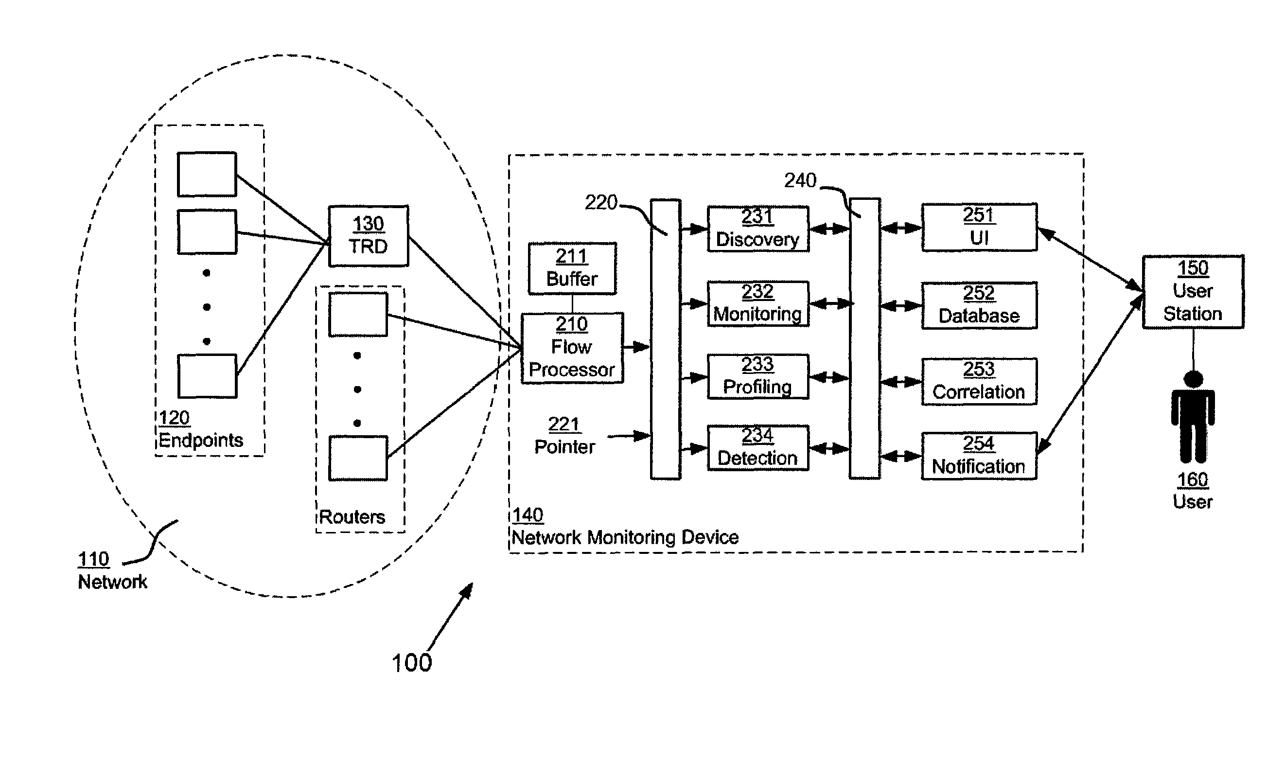
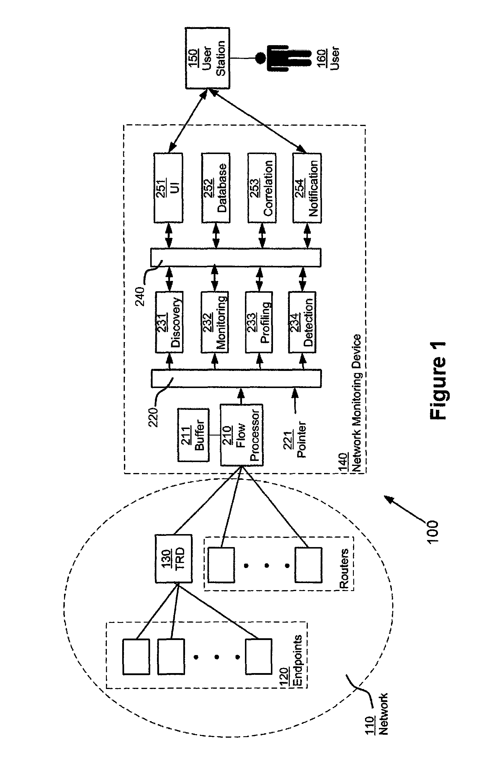
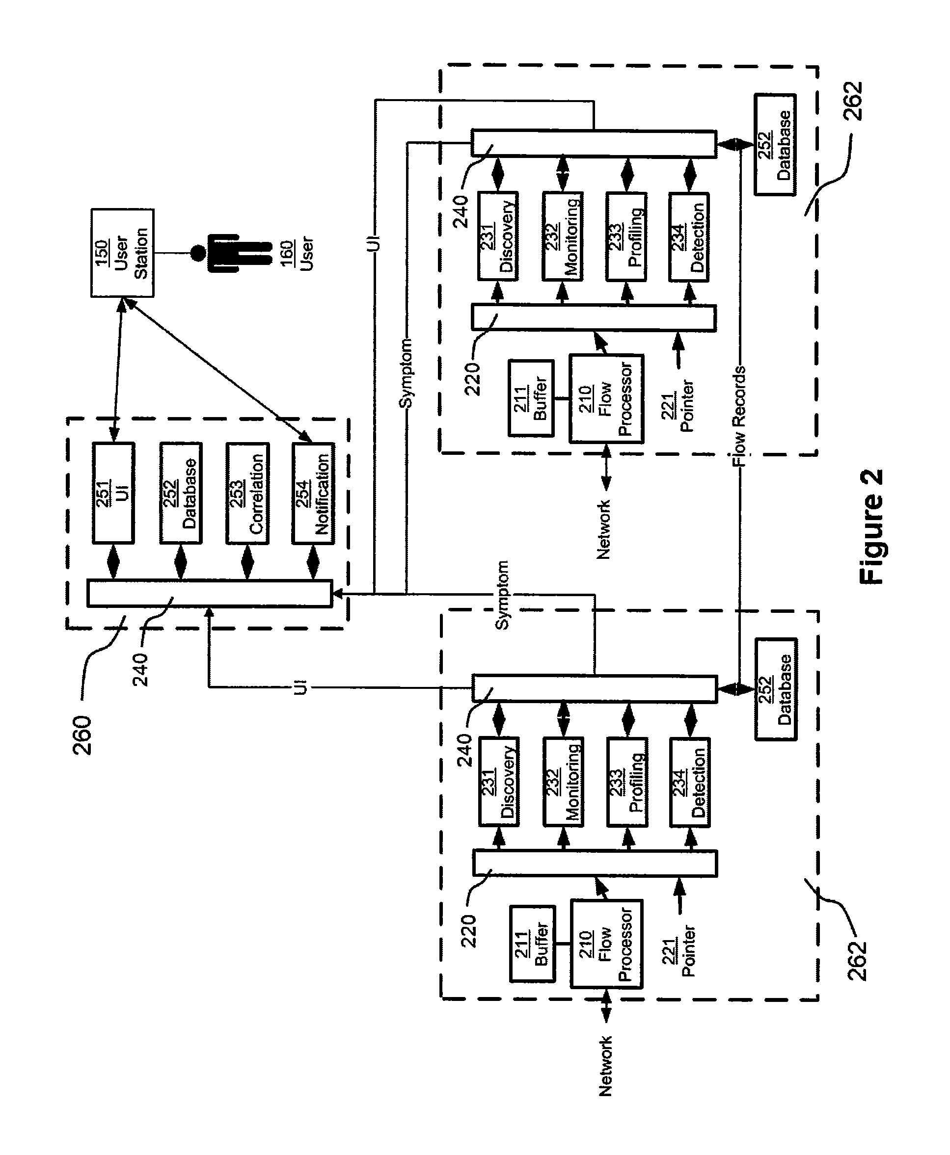
The network monitoring device can sample virtual packets in a way that balances information from different devices. This helps to get a complete picture of network activity. The device can also choose to focus on a smaller number of virtual packets, which helps to keep up with a large number of packets.

Problems solved by technology

Large scale network operations often experience technical malfunctions that degrade system performance.
For large networks, this degradation can be difficult to isolate because the problem can be located on remote devices or because the problem manifests itself not as a complete failure, but merely as poor performance.
Often, isolating a poor performing component is substantially more difficult than isolating one that has completely malfunctioned.
In traditional fault management the mean time to repair (MTTR) a problem is typically a couple of hours.
Given the difficulty with both identifying whether an application is degrading and what the source of the degradation is, the MTTR that is associated with application management can be quite lengthy.
The problems encountered range in scope and complexity depending on the source of the problems.
Some examples of network operations problems include sluggish mission-critical applications, the misuse of peer-to-peer applications, an underutilized load balance link, or lethargic intranet performance—all which have an adverse effect on network operations and eventually to on organization's productivity.
Consequently the scope and complexity of monitoring networks with a wide variety of applications, processes, and distribution points is growing and manufacturers of tools for maintaining network operations struggle to stay up-to-date.
One known problem is when monitoring network traffic for a relatively large network, the amount of information relating to that network traffic can also be relatively large.
The sheer volume of nodes and traffic in the network makes it more difficult for a network monitoring device to keep up with that relatively large amount of information.

Method used


Image

  • Network monitoring using virtual packets
  • Network monitoring using virtual packets
  • Network monitoring using virtual packets

Examples


examples of specific

Applications

[0071]The following examples of specific applications illustrate some aspects of the techniques previously discussed in conjunction with other techniques. It should be understood that this application is not limited to these specific examples. Also, the steps of any methods and / or techniques described below can be performed in a different order than shown, pipelined, threaded, or in other ways. Some steps might be omitted in some applications, and additional steps may be added.

Crosspoints

[0072]The term “crosspoint” generally describes an entity which can be determined by training, creating a baseline, and eventually detecting symptoms. Four types of crosspoints are generally profiled: IDs (named network endpoints), Applications, Locations, Interfaces, and Time Periods. Both incoming and outgoing activity for each of these crosspoints may be profiled.

[0073]ID and Application crosspoints may be automatically generated using a discovery process, followed by an object creati...


PUM


Abstract

A network monitoring device includes a flow processing element, disposed to receive flow information relating to network flows, and to generate a set of virtual packets, each representing a portion of a network flow. The virtual packets are maintained in a time-sequential order, and read by elements of the network monitoring device to generate information relating to network traffic, such as symptoms affecting the communication network, problems affecting the communication network, and otherwise. The network monitoring device randomly samples virtual packets, with at least one of two effects: (1) flow information from traffic reporting devices that are themselves sampling at differing rates can be equalized, with the effect of standardizing information from all of them; (2) the network monitoring device itself can restrict its attention to a fraction of all virtual packets, with the effect of keeping up with a relatively large number of virtual packets.

Description

CROSS-REFERENCE TO RELATED DOCUMENTS[0001]This application claims priority of the following related documents:[0002]U.S. Patent Application 60 / 962,295, filed Jul. 25, 2007 in the name of the same inventors, titled “Network Monitoring Using Virtual Packets”.[0003]U.S. Patent Application 60 / 962,181, filed Jul. 25, 2007 in the name of the same inventors, titled “Parallel Distributed Network Monitoring”.[0004]U.S. Patent Application 60 / 962,182, filed Jul. 25, 2007 in the name of the same inventors, titled “Network Monitoring Using Bounded Memory Data Structures”.[0005]Each of these documents is hereby incorporated by reference as if fully set forth herein.BACKGROUND[0006]Large scale network operations often experience technical malfunctions that degrade system performance. For large networks, this degradation can be difficult to isolate because the problem can be located on remote devices or because the problem manifests itself not as a complete failure, but merely as poor performance. ...

Claims


Application Information

Patent Timeline
Patent Type & Authority Patents(United States)
IPC IPC(8): H04J1/16H04J3/14G06F15/173
CPCH04L43/026H04L43/0817H04L43/04Y02B60/33Y02D30/50H04L43/20H04L41/0645H04L43/00H04L43/022
Inventor LEE, ROSANNAZHU, HONGJAGANNATHAN, RANGASWAMYPAN, XIAOHONGSANDERS, DEREKKAKATKAR, KISHORLIU, JING
Owner VIRTUAL INSTR CORP
Learn More