High-efficiency combustors with reduced environmental impact and processes for power generation derivable therefrom

a combustible and environmental protection technology, applied in the direction of solid fuel combustion, combustion types, lighting and heating apparatuses, etc., can solve the problems of further reducing specific thermodynamic efficiency, process only appears to be more complicated and costly, and inability to eliminate unfused incombustible particulates (fly ash)

Active Publication Date: 2013-06-04
ITEA SPA
View PDF15 Cites 82 Cited by
  • Summary
  • Abstract
  • Description
  • Claims
  • Application Information

AI Technical Summary

Problems solved by technology

However, unfused incombustible particulates (fly ash) are nevertheless still present and cannot be eliminated even by the higher temperature flames.
The process is only apparently more complicated and costly than prior art turbogas systems characterised by a very compact design of the base unit, axial compressor / annular chamber of combustors / expansion turbine.
Furthermore, the only way to control the power delivered is to throttle the fuel, which reduces the temperature of the combusted gases and so brings about a further reduction in specific thermodynamic efficiency.
The acknowledged rapid start-up time of prior art turbogas systems is in part offset by a clear lack of flexibility in operation.

Method used


Image

  • High-efficiency combustors with reduced environmental impact and processes for power generation derivable therefrom
  • High-efficiency combustors with reduced environmental impact and processes for power generation derivable therefrom
  • High-efficiency combustors with reduced environmental impact and processes for power generation derivable therefrom

Examples


example 2

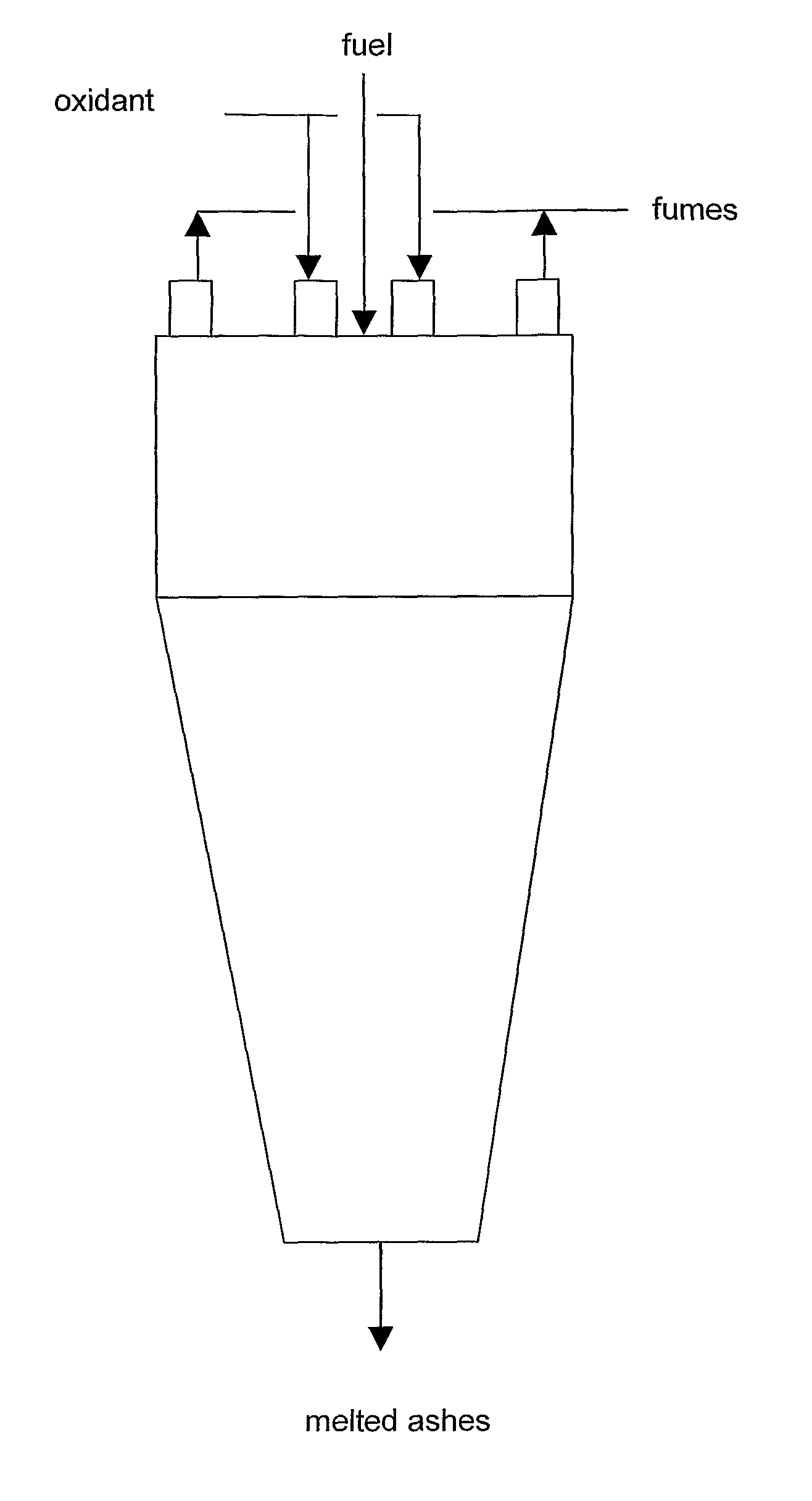
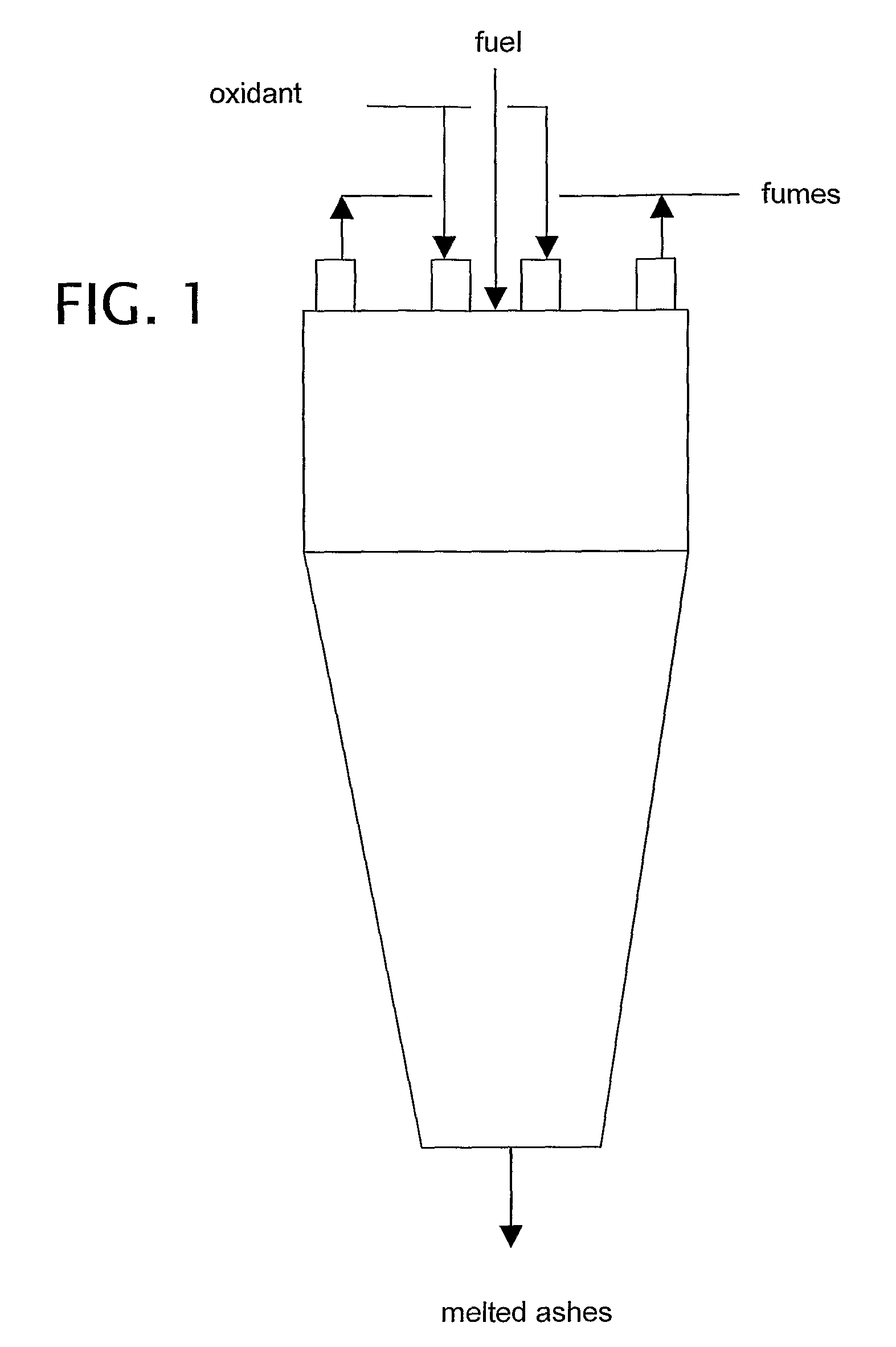
[0121]The preheated reactor of Example 1 is fed with light fuel and maintained at a pressure slightly above atmospheric. Over an 8 hour cycle, the fuel feed rate is gradually increased, from 1.5 litres / minute to 4 litres / minute, in order to increase the temperature of the flue gases from 1500 K to 2100 K with a gradient of 60-80 K / hour. Oxygen is fed to the reactor at a constant ratio to fuel, in such a manner as to maintain the excess of oxygen in the flue gases between 4 and 1.8 mol %. Recycled fumes are adjusted to allow an increase in the temperature of the flue gases.

[0122]The following changes in emissions were observed (obviously notwithstanding the scattering of the data):

[0123]

T flue gasesNO ppmCO ppmTOC ppmat1500 K2504051900150151210028051

[0124]A wide visible flame zone, close to the feed zone, was observed through the quartz porthole. The flame zone shrinks progressively and disappears at above 2000 K.

example 3

[0125](as Example 2, but at a Pressure of 400 kPa Absolute)

[0126]The following changes were observed:

[0127]

T flue gasesNO ppmCO ppmTOC ppmat1500 K501521900305121009051

[0128]The flame zone is small from the beginning and disappears at 1700 K.

example 4

[0129](as Example 1, but at a Pressure of 700 kPa Absolute)

[0130]The following changes were observed:

[0131]

T flue gasesNO ppmCO ppmTOC ppmat1500 K15511900305121009051

[0132]The flame zone is very limited at the beginning and rapidly disappears.


PUM


Abstract

A process for combusting solid liquid or gaseous fuels in a high temperature refractory-lined reactor with the aim of generating electric power comprises mixing at least one fuel with steam. The refactory material of the reactor and the opaque gases of the reaction environment bring about high power infrared radiation which substantially instantaneously preheats the reactants on input including said reactants being intrinsically transparent to infrared radiation (N2 / O2) but rendered opaque and thus absorbers of energy from infrared radiation thanks to dilution with steam. A high efficiency combustor is provided for carrying out the above-stated process.

Description

CROSS-REFERENCE TO RELATED APPLICATION[0001]This application is a National Stage entry of International Application No. PCT / IB2005 / 001290, filed May 11, 2005, the entire specification claims and drawings of which are incorporated herewith by reference.BACKGROUND OF THE INVENTION[0002]Research and applications technology relating to the combustion of fossil fuel with an oxygen oxidant (from air to cryogenic grade), namely to flames, are of great relevance for the quantitative impact on the environment, and for the power generation economic impact on the development.[0003]With the specific aim of reducing environmental impact, there has been a progressive shrinkage of the flame operating temperature range, though temperature being the most significant variable with regard to productivity. Threshold temperature limits has been put to limit toxic organic compounds (dioxins, furans, polyaromatic hydrocarbons (PAH)), as well as ceiling T values have been set to limit green-house gas (NOX)...

Claims


Application Information

Patent Timeline
Patent Type & Authority Patents(United States)
IPC IPC(8): F23B80/02F23C9/00B09B3/00F23L7/00F23G5/00
CPCF23L7/00F23C2900/99001Y02E20/12Y02E20/344Y02E20/342Y02E20/34
Inventor MALAVASI, MASSIMOROSSETTI, EDOARDO
Owner ITEA SPA
Why Eureka
Try Eureka